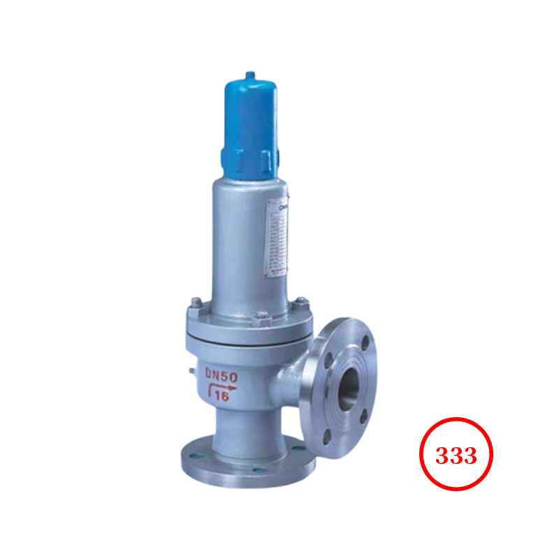
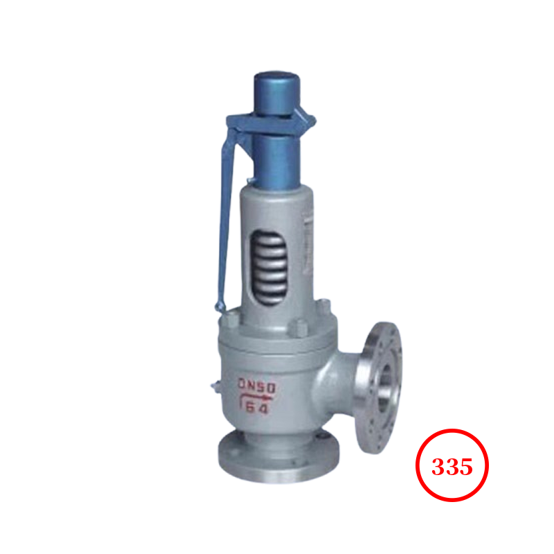
本阀适用于工作温度≤120℃有腐蚀性介质的设备管路上,作为超压保护装置。本阀适用于:化工、、有毒介质的管线系统,高危腐蚀性介质受压设备、压力容器及管路上的自动压力释放装置。valve body进行内衬四氟(PFAF46),在关键部分采用全四氟(PTFEF46)material,增加了耐腐蚀性能,可有效防止、盐酸、强腐蚀性等介质腐蚀。
本阀特别适用于:
1、作为昂贵的稀有金属(哈氏、钛、镍、蒙乃尔、钽合金)阀门的代替品。
2、用于对环境有毒、有害的腐蚀性介质。
3、用于与金属反应的介质,如盐酸、等高危介质。
4、用于生物工程和纯净介质中要求洁净及表面抗粘附的场合。
5、用于高渗透性的介质。
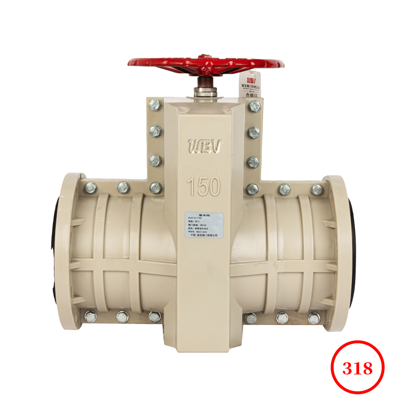
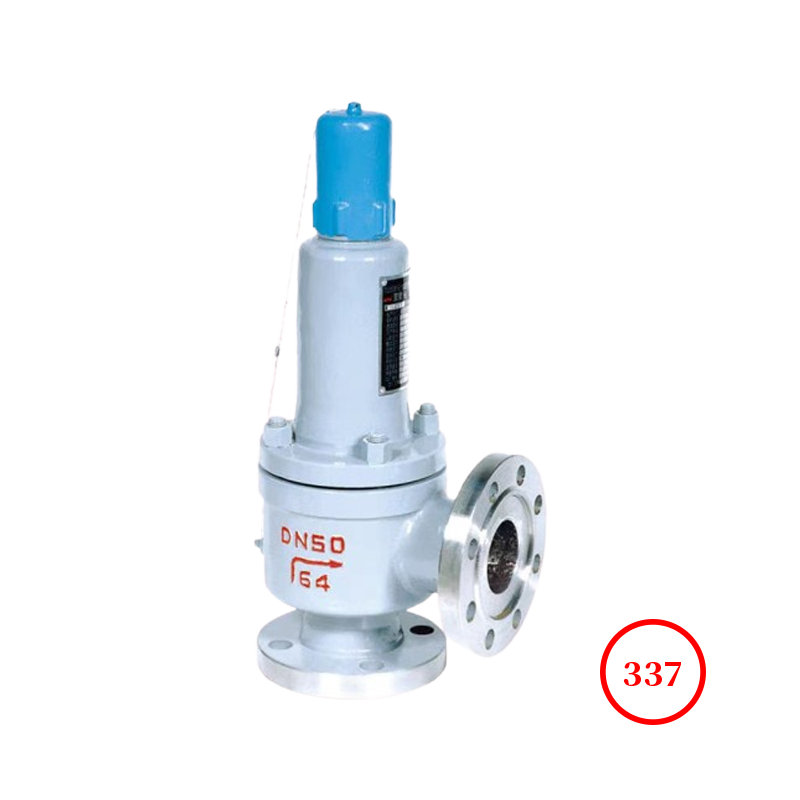
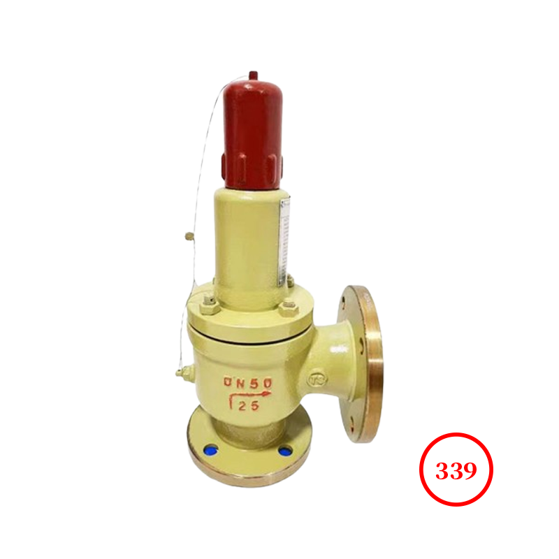
Product drawing

Product dimensions
| model | DN | D | K | g1 | b | f | f1 | Z-Φd | DN' | D1 | K1 | g2 | b1 | Z1-Φd1 | L | L1 |
| A42F46-16C/P/R | 25 | 115 | 85 | 65 | 16 | 2 | 2 | 4-14 | 32 | 140 | 100 | 78 | 18 | 4-18 | 110 | 95 |
| 32 | 140 | 100 | 78 | 18 | 2 | 2 | 4-18 | 40 | 150 | 110 | 85 | 18 | 4-18 | 115 | 110 |
| 40 | 150 | 110 | 85 | 18 | 3 | 3 | 4-18 | 50 | 165 | 125 | 100 | 18 | 4-18 | 120 | 110 |
| 50 | 165 | 125 | 100 | 20 | 3 | 3 | 4-18 | 65 | 185 | 145 | 120 | 20 | 4-18 | 135 | 120 |
| 80 | 200 | 160 | 135 | 20 | 3 | 3 | 8-18 | 100 | 220 | 180 | 155 | 22 | 8-18 | 170 | 140 |
| 100 | 220 | 180 | 155 | 22 | 3 | 3 | 8-18 | 125 | 250 | 210 | 185 | 22 | 8-18 | 195 | 175 |
| 150 | 285 | 240 | 210 | 24 | 3 | 3 | 8-23 | 175 | 310 | 270 | 240 | 26 | 8-23 | 255 | 230 |
| A42F46-25C/P/R | 25 | 115 | 85 | 65 | 16 | 2 | 2 | 4-14 | 32 | 140 | 100 | 78 | 18 | 4-18 | 110 | 95 |
| 32 | 140 | 100 | 78 | 18 | 2 | 2 | 4-18 | 40 | 150 | 110 | 85 | 18 | 4-18 | 115 | 110 |
| 40 | 150 | 110 | 85 | 18 | 3 | 3 | 4-18 | 50 | 165 | 125 | 100 | 20 | 4-18 | 120 | 110 |
| 50 | 165 | 125 | 100 | 20 | 3 | 3 | 4-18 | 65 | 185 | 145 | 120 | 20 | 4-18 | 135 | 120 |
| 80 | 200 | 160 | 135 | 22 | 3 | 3 | 8-18 | 100 | 220 | 180 | 155 | 22 | 8-18 | 170 | 135 |
| 100 | 230 | 190 | 160 | 24 | 3 | 3 | 8-23 | 125 | 250 | 210 | 185 | 22 | 8-28 | 195 | 175 |
Technical Documentation
1.设计制造标准:GB/T 12243-2021
2.Structural length standard:GB/T12221-2005
3.Flange Standard:GB/T9113.1-2000
4.试验标准:GB/T13927-2022
Product Parts List
| name | material |
| valve bodymaterial | WCB、316SS、内衬(F46、PO、PFA)用户要求 |
| valve discmaterial | WCB、316SS、内衬(F46、Po、PFA)用户要求 |
| valve seatmaterial | WCB、316SS、内衬(F46、Po、PFA)用户要求 |
| springmaterial | 304SS、F304、A182、50CrVA、316SS |
| 导向material | WCB、316SS、内衬(F46、Po、PFA)用户要求 |
| 阀索material | WCB、316SS、内衬(F46、Po、PFA)用户要求 |
| 调节圏material | PTFE、F46、PFA |
安装与调试注意事项
(1)安全阀应与容器本体直接连接并装在容器高处,对液化气储槽上的安全阀应装在气相空间,用于液体的安全阀应装在正常液面以下,而且安全阀进口管的公称直径不得小于15mm。因特殊原因难以装在容器本体上时,可考虑装在出口管路上,但安全阀装设处与容器之间的管路上应避免突然拐弯、截面局部收缩等结构,防止增加管路阻力、引起污物积聚发生堵塞等。
(2)无论安全阀装在何处,在从容器到安全阀之间的连接管和管件通孔其截面积均不得小于安全阀的进口面积。如果一个连接口上装有数个安全阀,则此连接口的面积至少应等于数个阀进口面积的总和,是总和的1.25倍。
(3)在容器与安全阀之间一般禁止装设中间截止阀,但对于盛装易燃、有毒或粘性较大介质的容器,为便于对安全阀进行更换、清洗,可以在容器和安全阀之间装截止阀,但此截止阀的结构和pathsize不得阻碍安全阀的正常泄放,当容器正常工作时,该截止阀必须处于全开状态并加铅封。
(4)安全阀后的排放管如有出现冷凝液体的可能,则应考虑有自动排除设施;封闭式安全阀排放管的内径不得小于安全阀出口管的公称直径。排放管原则上应一阀一根,并禁止在排放管上装任何阀门,当两个以上安全阀共用同一根排放管时,排放管的截面积应不小于所有安全阀出口管截面积的总和,并适当考虑排放管的压力降,不使安全阀产生明显的背压。对氧气等可燃性气体或其他混合后能发生化学反应的气体不能共用一根排气管。
(5)新安全阀在安装之前应在试验台上调定其开启压力和回座压力,并检查关闭件的密封性。开启压力可通过调节加在valve disc上的载荷,如杠杆式安全阀的重锤质量或位置,spring式安全阀压紧spring的nut的位置(在正确选择spring压力级的基础上),回座力可通过调整安全阀的上下Adjustment Circle的位置来达到。
使用与管理
选择得当、安装正确的安全阀还应通过合理地使用和管理才能发挥其作用。日常使用中,为确保安全阀的良好工作状态,应加强维护与检查,保持valve body清洁,防止valve body及spring锈蚀,防止valve body被油垢、异物堵塞,要经常检查阀的铅封是否完好,防止杠杆式安全阀的重锤松动或被移动、spring式安全阀调节nut被随意拧动,发现泄漏应及时更换或检修,禁止用加大载荷(如过分拧紧spring式安全阀的调节nut,或在杠杆式安全阀的杠杆上加重物等)的方法消除泄漏。为了防止valve disc与valve seat被气体中的油垢等脏物粘住,对用于空气、水蒸气或更带有粘性脏物但排放时不会造成环境污染的其他气体的安全阀,应定期扳动扳手进行入工排气,以冲刷污物。
安全阀应定期进行检验,包括开启压力、回座压力、密封程度等,其要求与安全阀的调试相同。当检验不合格时应解体,详细检查各零部件是否有裂纹、伤痕、磨损、腐蚀、变形等,并进行修复或更换后组装再进行检查。安全阀定期检验的周期可与所用的容器检验周期相同。