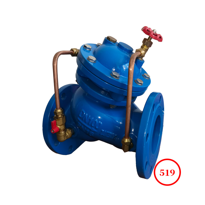
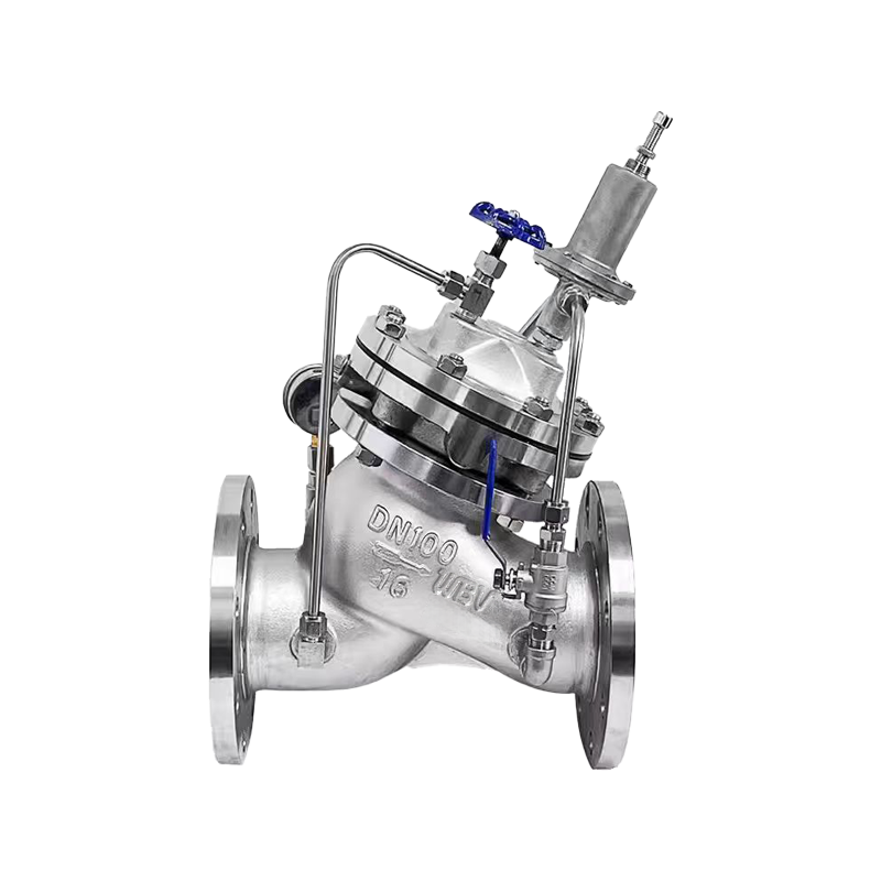
The water pump control valve is a check valve installed at the outlet of the water pump to prevent the backflow of the medium. Before the water pump is about to stop supplying water, the valve should be slowly closed by about 90% to prevent water hammer and water hammer sound caused by sudden pump stop. After the water pump stops, the valve should be closed to prevent the backflow of pumped water, effectively protecting the water pump from the impact of backflow and reversal. This product is a protective device for the outlet of the water pump. The valve is designed with a streamlined shape, and accurate opening and closing are achieved through the guidance of an electromagnetic valve. It is reliable to use, effectively prevents water hammer and water hammer sound, has a long service life, and is easy to install and maintain.
When the water pump starts supplying water through the valve, the solenoid valve is first energized and opened. The water enters the main valve control room through the needle valve and check valve (1), flows through the solenoid valve and ball valve to the outlet, and the pressure in the upper chamber of the main valve diaphragm decreases. The other route is that the check valve (2) on the conduit is closed, and the medium cannot flow out. Under the pressure difference between the upper and lower chambers of the diaphragm, the main valve core opens and normal water supply begins.
When the water supply needs to be stopped, the solenoid valve closes, the upper chamber of the main valve diaphragm stops draining, the pressure in the control room increases, and the main valve core begins to close. When it is closed to 90%, the upper stroke switch of the main valve outputs a pump stop signal, and the water pump stops running. At this time, the downstream return water enters the main valve control room through check valve (2). Due to the closure of check valve (1), the medium in the upper chamber of the diaphragm cannot flow out, and the pressure in the chamber increases. The main valve gradually closes.
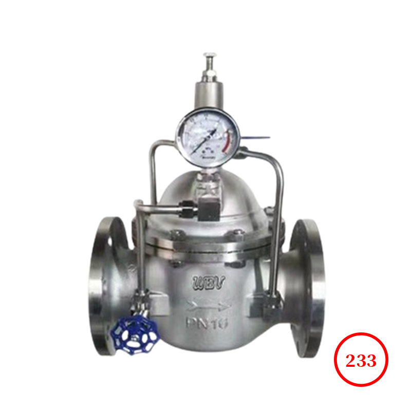
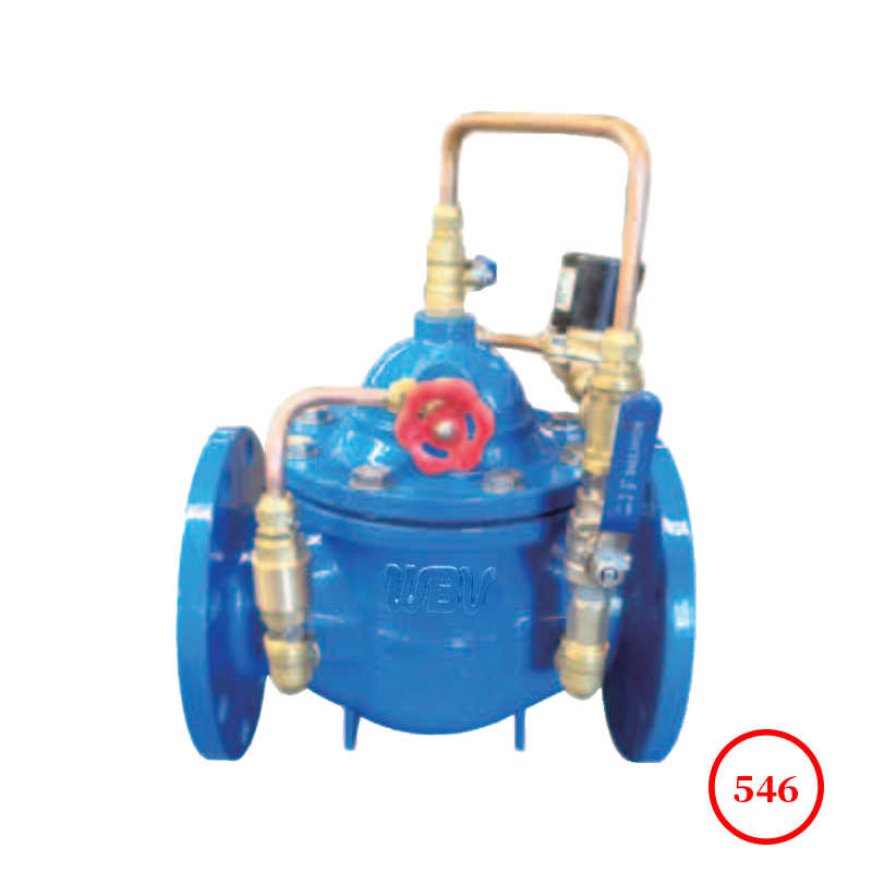
Product drawing

Product dimensions
| DN | L | A | A1 | H | H1 | F | D | D1 | D2 | n-Фd |
| PN1.0 | PN1.6 | PN2.5 | PN1.0 | PN1.6 | PN2.5 | PN1.0 | PN1.6 | PN2.5 | PN1.0 | PN1.6 | PN2.5 |
| 20 | 180 | 194 | 136 | 342 | 250 | 116 | 105 | 105 | 105 | 75 | 75 | 75 | 58 | 58 | 56 | 4-13.5 | 4-13.5 | 4-14 |
| 25 | 180 | 194 | 136 | 342 | 250 | 116 | 115 | 115 | 115 | 85 | 85 | 85 | 68 | 68 | 65 | 4-13.5 | 4-13.5 | 4-14 |
| 32 | 180 | 194 | 136 | 342 | 250 | 116 | 140 | 140 | 140 | 100 | 100 | 100 | 78 | 78 | 76 | 4-17.5 | 4-17.5 | 4-18 |
| 40 | 240 | 240 | 155 | 395 | 278 | 170 | 150 | 150 | 150 | 110 | 110 | 110 | 88 | 88 | 84 | 4-17.5 | 4-17.5 | 4-18 |
| 50 | 240 | 240 | 155 | 395 | 278 | 170 | 165 | 165 | 165 | 125 | 125 | 125 | 102 | 102 | 99 | 4-17.5 | 4-17.5 | 4-18 |
| 65 | 255 | 255 | 165 | 405 | 298 | 180 | 185 | 185 | 185 | 145 | 145 | 145 | 122 | 122 | 118 | 4-17.5 | 4-17.5 | 8-18 |
| 80 | 280 | 280 | 175 | 430 | 315 | 210 | 200 | 200 | 200 | 160 | 160 | 160 | 133 | 133 | 132 | 8-17.5 | 8-17.5 | 8-18 |
| 100 | 360 | 332 | 195 | 510 | 350 | 275 | 220 | 220 | 235 | 180 | 180 | 190 | 158 | 158 | 156 | 8-17.5 | 8-17.5 | 8-22 |
| 125 | 400 | 375 | 220 | 560 | 365 | 310 | 250 | 250 | 270 | 210 | 210 | 220 | 184 | 184 | 184 | 8-17.5 | 8-17.5 | 8-26 |
| 150 | 455 | 408 | 230 | 585 | 420 | 355 | 285 | 285 | 300 | 240 | 240 | 250 | 212 | 212 | 211 | 8-22 | 8-22 | 8-26 |
| 200 | 585 | 485 | 255 | 675 | 450 | 460 | 340 | 340 | 360 | 295 | 295 | 310 | 268 | 268 | 274 | 8-22 | 12-22 | 12-26 |
| 250 | 650 | 550 | 300 | 730 | 470 | 500 | 395 | 405 | 425 | 350 | 355 | 370 | 320 | 320 | 330 | 12-22 | 12-26 | 12-30 |
| 300 | 800 | 630 | 340 | 760 | 490 | 580 | 445 | 460 | 485 | 400 | 410 | 430 | 370 | 370 | 389 | 12-22 | 12-26 | 16-30 |
| 350 | 860 | 735 | 415 | 840 | 526 | 640 | 505 | 520 | 555 | 460 | 470 | 490 | 430 | 430 | 448 | 16-22 | 16-26 | 16-33 |
| 400 | 960 | 788 | 430 | 910 | 570 | 715 | 565 | 580 | 620 | 515 | 525 | 550 | 482 | 482 | 503 | 16-26 | 16-30 | 16-36 |
| 450 | 1075 | 850 | 460 | 1070 | 610 | 780 | 615 | 640 | 670 | 565 | 585 | 600 | 532 | 550 | 548 | 20-26 | 20-30 | 20-36 |
| 500 | 1075 | 905 | 490 | 1135 | 665 | 830 | 670 | 715 | 730 | 620 | 650 | 660 | 585 | 585 | 609 | 20-26 | 20-33 | 20-36 |
| 600 | 1230 | 970 | 530 | 1270 | 725 | 920 | 780 | 840 | 845 | 725 | 770 | 770 | 685 | 685 | 720 | 20-30 | 20-36 | 20-39 |
| 700 | 1650 | 1050 | 560 | 1460 | 865 | 980 | 895 | 910 | 960 | 840 | 840 | 875 | 800 | 800 | 820 | 24-30 | 24-36 | 24-42 |
| 800 | 1750 | 1135 | 610 | 1640 | 975 | 1050 | 1015 | 1025 | 1085 | 950 | 950 | 990 | 905 | 905 | 928 | 24-33 | 24-39 | 24-48 |
Technical Documentation
1. Product design standard: CJ/T219-2005
2. Structural length standard: GB/T12221-2005
3. Flange standard: GB/T9113.1-2000
4. Test standard: GB/T13927-2022
Product Parts List
| serial number | name | material | serial number | name | material |
| 1 | screw plug | CF8/WCB | 11 | rings | CF8/WCB |
| 2 | valve body | CF8/WCB | 12 | Electromagnetic guide valve | assembly |
| 3 | valve stem | CF8/2Cr13 | 13 | One-way check valve | CF8 |
| 4 | nut | CF8/A105 | 14 | compression spring | 50CrVA |
| 5 | sealing ring | NBR | 15 | limit switch | assembly |
| 6 | Valve disc | CF8/WCB | 16 | One-way check valve | CF8 |
| 7 | Diaphragm pressure plate | CF8/WCB | 17 | Studs and nuts | CF8 |
| 8 | Rubber film | EPDM | 18 | needle valve | CF8 |
| 9 | ball valve | CF8 | 19 | pressure gauge | assembly |
| 10 | valve cover | CF8/WCB | 20 | Micro filter | CF8 |
Installation and maintenance
1. The main valve should be installed on the inlet pipe of the water tank or high water level water tower. The installation method is to horizontally install it on the pipeline with the valve cover facing upwards. Other installation methods can also achieve the operating function. Pay attention to the flow direction indicated by the arrow outside the main valve body and install it in the correct direction. After installation, ensure that there is no pipeline stress acting on the valve body and internal components.
2. Before installation, remove any debris from the pipeline and flush the piping system before passing water.
3. A gate valve and a filter should be installed in front of the main valve, and a gate valve should also be installed behind the valve for easy maintenance.
4. When testing the water, slowly open the gate valve in front of the main valve to increase the pressure, and pay attention to whether the control pipeline outside the valve body is leaking.
5. The micro filter on the main valve conduit should be cleaned regularly every 2-3 months.
Main valve maintenance instructions
The hydraulic control valve itself is a water self lubricating valve body that does not require additional oil lubrication. If the internal parts of the main valve are damaged, please follow the following instructions for disassembly. (Note: The commonly vulnerable consumables inside the main valve are the diaphragm and O-ring, and other internal metals are rarely damaged.)
1. Close the front and rear gate valves of the main valve first.
2. Loosen the piping joint screws on the main valve cover to release the pressure inside the valve.
3. Remove all screws, including necessary copper pipes and nuts in the control pipeline.
4. Remove the valve cover and spring.
5. Remove the shaft core, diaphragm (piston), etc., and do not damage the diaphragm.
6. After removing the above items, check whether the diaphragm and O-ring are damaged. If they are not damaged, do not disassemble their internal parts again.
7. If damage is found on the diaphragm or O-ring, loosen the nut on the shaft core, disassemble the worship plate or sealing gasket piece by piece, and replace it with a new diaphragm or sealing gasket after removal.
8. Carefully inspect the valve seat and shaft core inside the main valve for any damage. If there are any other debris inside the main valve, clean it out.
9. Combine the replaced parts in reverse order and install the main valve, paying attention to the valve not being stuck.
10. Please refer to the installation sequence for reuse. Thank you for your cooperation!