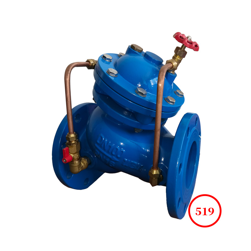
Structural characteristics:
This product consists of a main valve, a pressure relief pilot valve, a ball valve, and a connecting system. The main valve adopts a full channel, DC, streamlined design, and adopts two types of structures: diaphragm or piston. This valve uses a pressure relief pilot valve to set the pressure relief, and adjusting the spring of the pilot valve can set different pressure relief values. Control the valve opening and closing through the main valve control room to achieve pressure relief function. This product is independently controlled by the main valve, pressure relief pilot valve, and connecting system for water pressure, without the need for additional devices or energy sources. The structure is simple and reliable, with accurate pressure control and easy maintenance.
Job characteristics
By transmitting pressure through hydraulic conduits, the sliding disc (valve disc) of the main valve imitates the action of the pilot valve. As long as the upstream pressure is lower than the set value of the pilot valve, the pilot valve closes and the upstream pressure acts on the diaphragm, keeping the main valve closed. Once the upper pressure rises above the set pressure of the pilot valve, the pilot valve opens and releases a large amount of water to reduce the pressure to the set value before slowly and smoothly closing without generating secondary water hammer.
1. Close tightly and reliably. The main valve seal adopts a rubber sealing ring seal, and the closing power is automatically formed by the main valve control room to maintain appropriate closing force, with high sealing life and reliability.
2. Easy to operate, no need to equip the valve with an electrical control system or other additional devices.
3. Control pressure without being affected by factors such as flow rate to ensure accurate pressure relief.
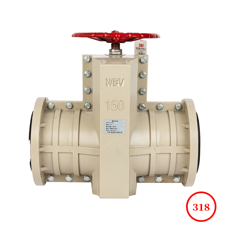
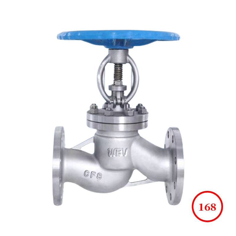
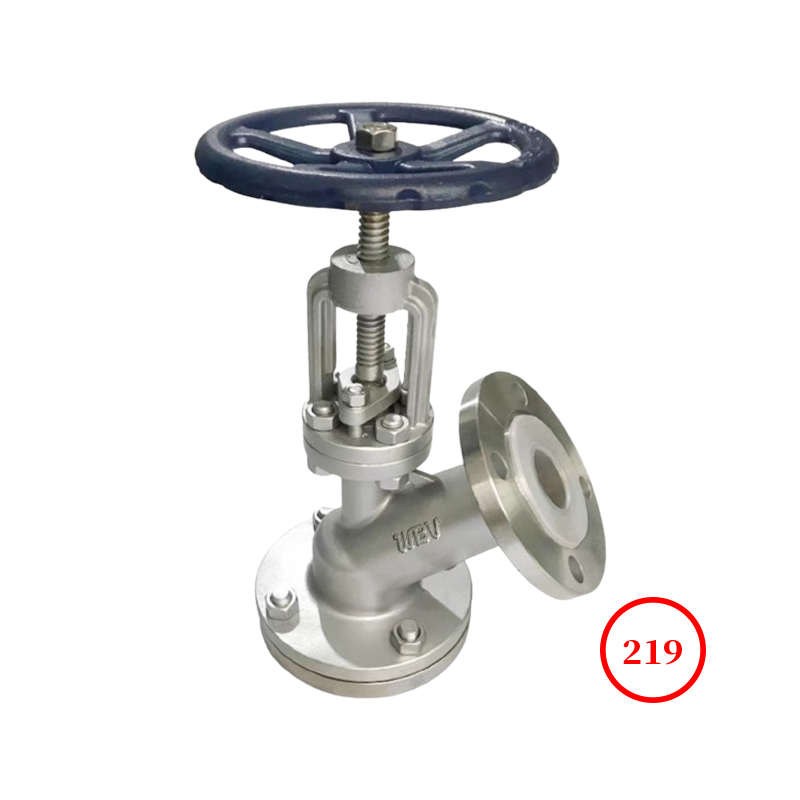
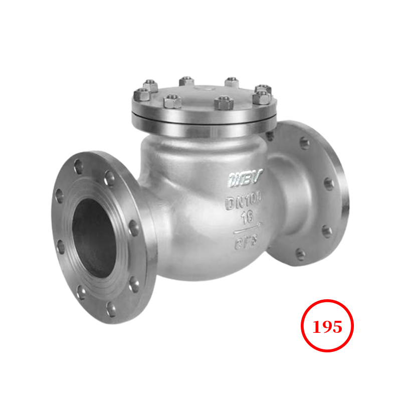
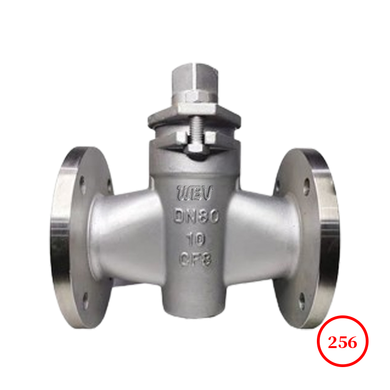
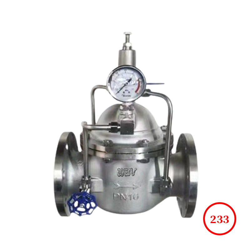
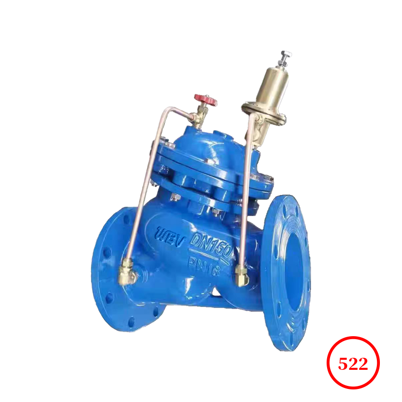
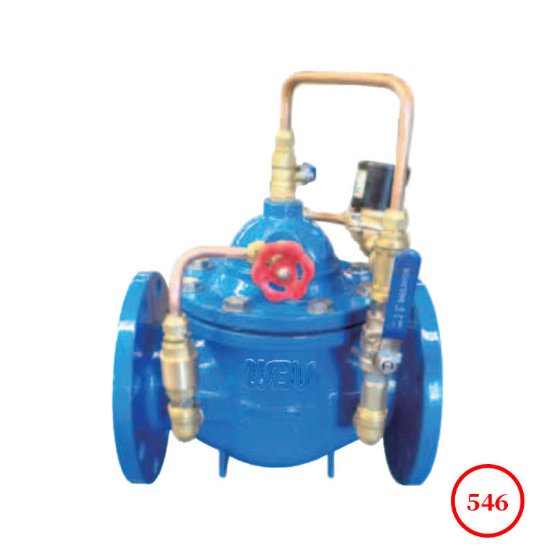
Product drawing

Product dimensions
| DN | L | PN10 | PN16 | PN25 |
| D | D1 | Z-Фd | D | D1 | Z-Фd | D | D1 | Z-Фd |
| 50 | 205 | 165 | 125 | 4-Ф18 | 165 | 125 | 4-Ф18 | 165 | 125 | 4-Ф18 |
| 65 | 208 | 185 | 145 | 4-Ф18 | 185 | 145 | 4-Ф18 | 185 | 145 | 4-Ф18 |
| 80 | 240 | 200 | 160 | 8-Ф18 | 200 | 160 | 8-Ф18 | 200 | 160 | 8-Ф18 |
| 100 | 280 | 220 | 180 | 8-Ф18 | 220 | 180 | 8-Ф18 | 235 | 190 | 8-Ф22 |
| 125 | 355 | 250 | 210 | 8-Ф18 | 250 | 210 | 8-Ф18 | 270 | 220 | 8-Ф26 |
| 150 | 362 | 285 | 240 | 8-Ф22 | 285 | 240 | 8-Ф22 | 300 | 250 | 8-Ф26 |
| 200 | 420 | 340 | 295 | 8-Ф22 | 340 | 295 | 12-Ф22 | 360 | 310 | 12-Ф26 |
| 250 | 520 | 395 | 350 | 12-Ф22 | 405 | 355 | 12-Ф26 | 425 | 370 | 12-Ф30 |
| 300 | 595 | 445 | 400 | 12-Ф22 | 460 | 410 | 12-Ф26 | 485 | 430 | 12-Ф30 |
| 350 | 620 | 505 | 460 | 16-Ф22 | 520 | 470 | 16-Ф26 | 555 | 490 | 16-Ф33 |
| 400 | 710 | 565 | 515 | 16-Ф22 | 580 | 525 | 16-Ф30 | 620 | 550 | 16-Ф36 |
| 450 | 780 | 615 | 565 | 20-Ф26 | 640 | 585 | 20-Ф30 | 670 | 600 | 20-Ф36 |
| 500 | 815 | 670 | 620 | 20-Ф26 | 715 | 650 | 20-Ф33 | 730 | 660 | 20-Ф36 |
| 600 | 895 | 780 | 725 | 20-Ф30 | 840 | 770 | 20-Ф36 | 845 | 770 | 20-Ф39 |
| 700 | 1195 | 890 | 840 | 24-Ф30 | 910 | 840 | 24-Ф36 | 960 | 875 | 24-Ф42 |
| 800 | 1320 | 1015 | 950 | 24-Ф33 | 1025 | 950 | 24-Ф39 | 1025 | 990 | 24-Ф48 |
| 1000 | 1310 | 1230 | 1160 | 28-Ф36 | 1485 | 1170 | - | - | - | - |
| 1200 | 1500 | 1455 | 1380 | 32-Ф38 | - | - | - | - | - | - |
Technical Documentation
1. Product design standard: CJ/T219-2005
2. Structural length standard: GB/T12221-2005
3. Flange standard: GB/T9113.1-2000
4. Test standard: GB/T13927-2022
Product Parts List
| serial number | name | material | serial number | name | material |
| 1 | Valve body and valve cover | WCB/CF8 | 6 | Cylinder liner piston (piston type) | 2Cr13 |
| 2 | Valve seat disc | H59-1/2Cr13/Q235/CF8 | 7 | Diaphragm (Diaphragm type) | NBR |
| 3 | Sealing ring O-ring | NBR | 8 | Regulating valve ball valve | H59-1/CF8 |
| 4 | valve stem | 2Cr13/CF8 | 9 | filter | CF8 |
| 5 | spring | 50CrVA | - | - | - |
Installation and Debugging
1. The best installation method for the main valve is to install it on a horizontal pipeline with the valve cover facing upwards.
2. When installing, pay attention to the arrow indicating the water flow outside the valve body and follow the direction for installation. Pay attention to the arrow indicating the water flow outside the valve body and install it according to the direction.
3. Before installation, the debris inside the pipeline must be thoroughly removed, and the pipeline must be thoroughly cleaned before water is supplied.
4. A gate valve and a filter should be installed in front of the valve, and a gate valve should also be installed behind the valve (see installation diagram) for ease of maintenance.
5. When used as a pressure relief valve, the main valve is installed in the pressure relief bypass (see installation diagram).
6. When used as a pressure holding valve, the main valve is installed in series in the pipeline.
7. When adjusting pressure, first loosen the locking nut of the regulating screw of the pilot valve, turn the regulating screw of the pilot valve clockwise to increase pressure, and vice versa to decrease pressure. After adjustment, tighten the regulating screw.
8. Copper filters need to be cleaned regularly.