Welcome to Wenbao Valve Co., Ltd Official website E-mail:sales@wbvalve.com
Select :


- Home
- About
- Product
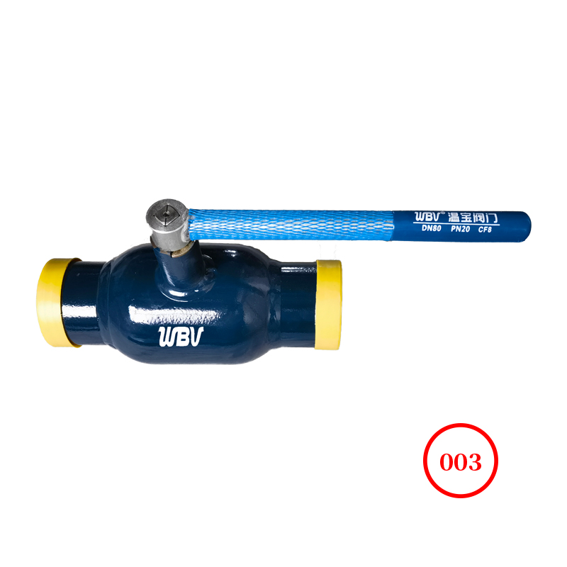
- Fully welded ball valve
- Forged steel ball valve
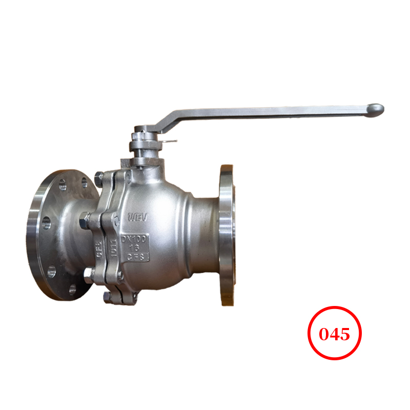
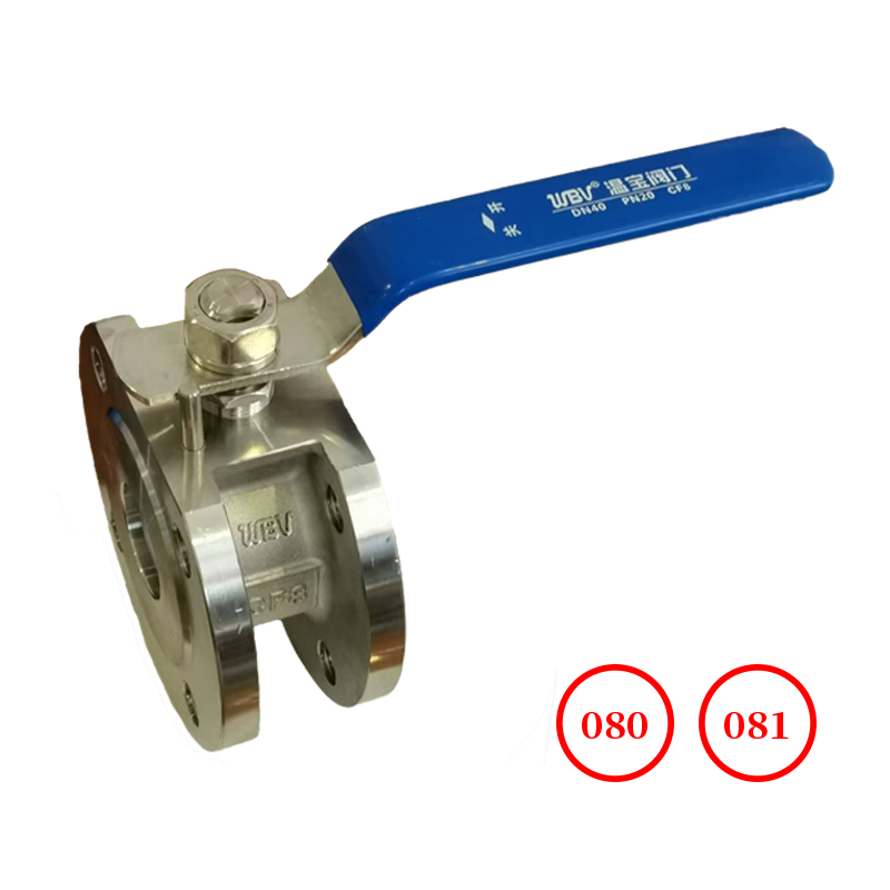
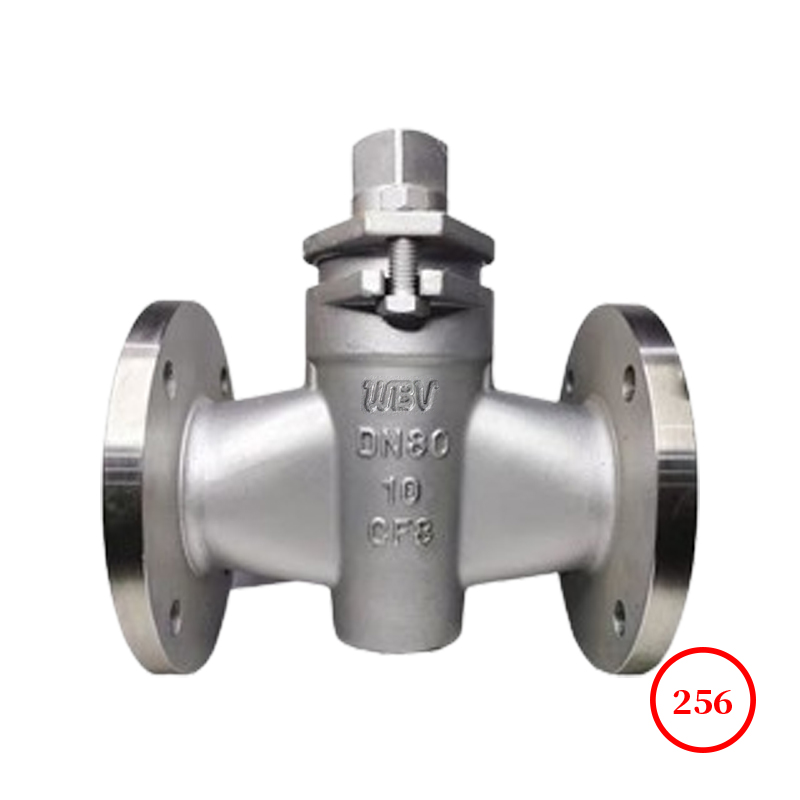
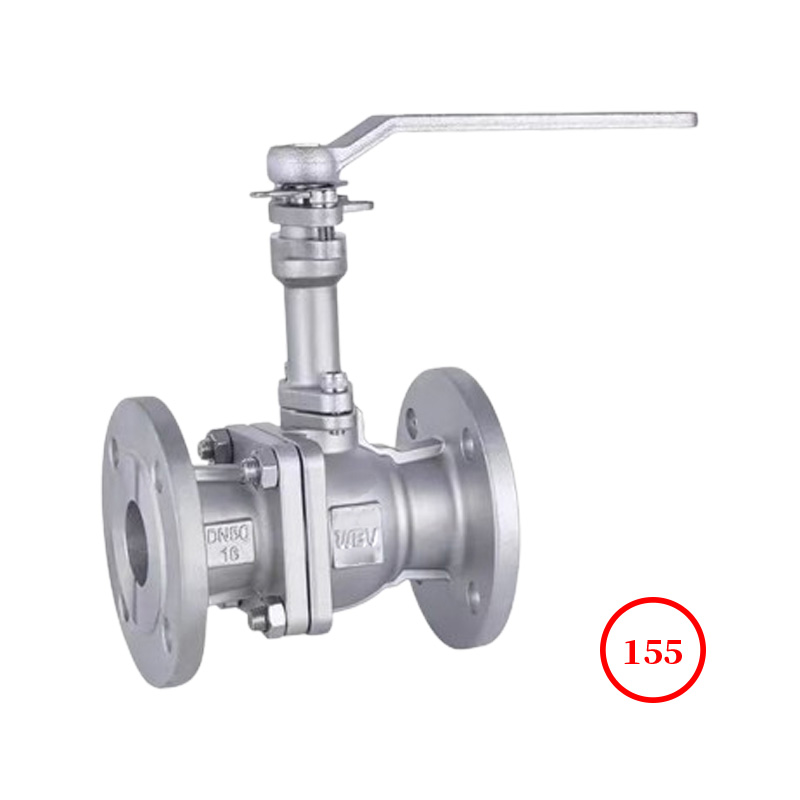
- Stainless steel ball valve
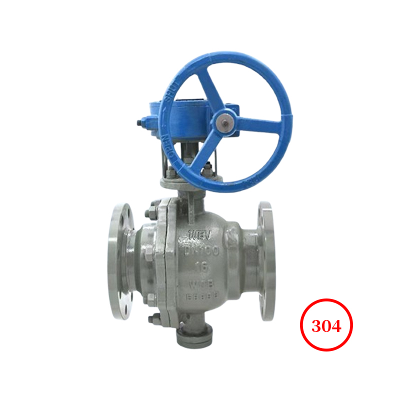
- Carbon Steel Ball Valve
- Clamp thin ball valve
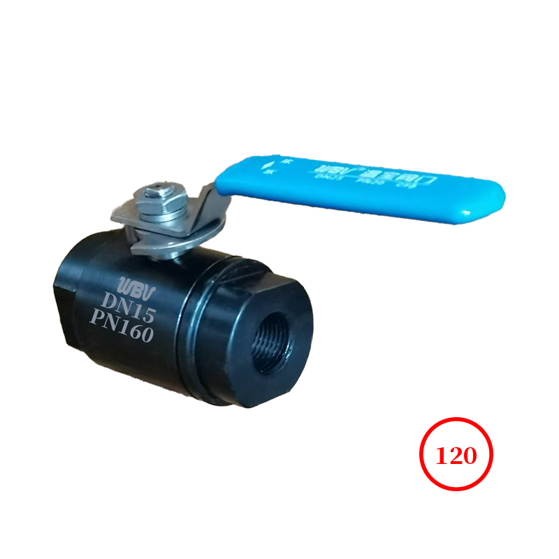
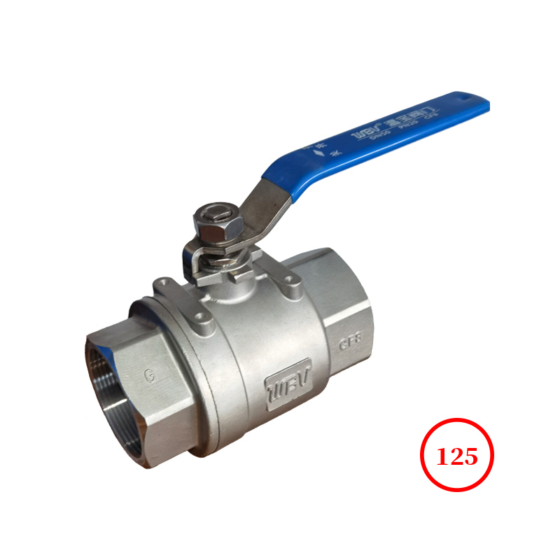
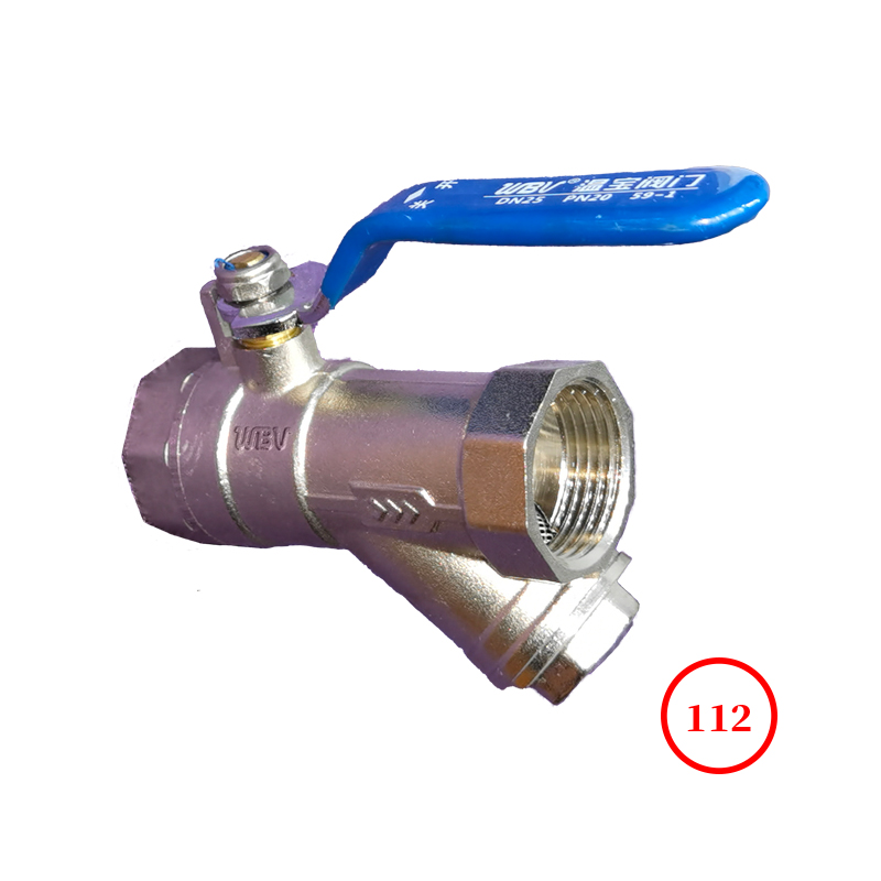
- Threaded connection ball valve
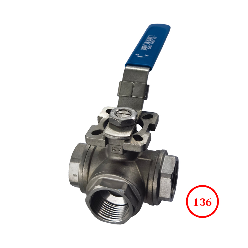
- Three-way ball valve
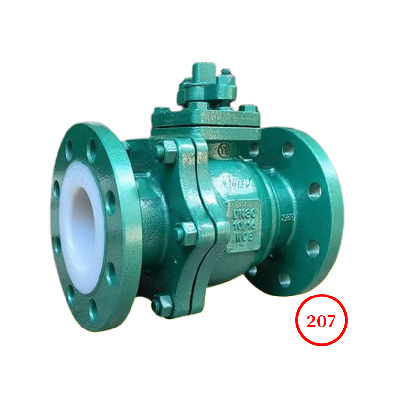
- Fluorine lined valve
- Pipe clamp valve
- Gate valve
- Flat Gate valve
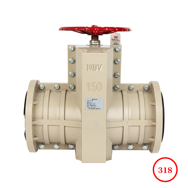
- Knife Gate valve
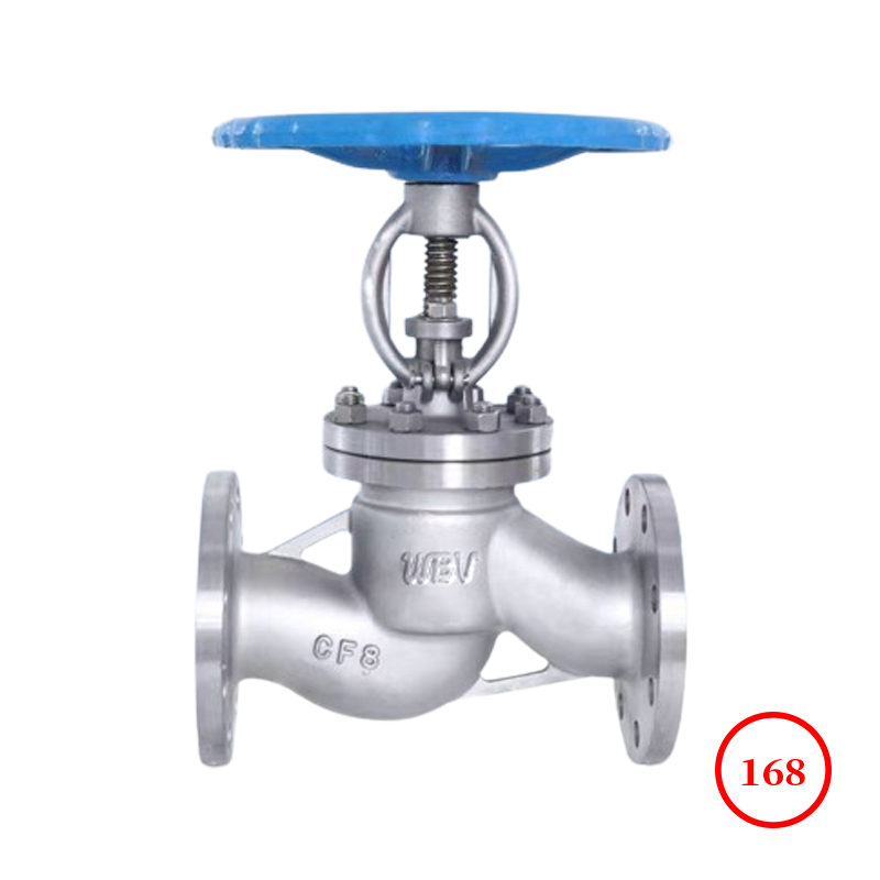
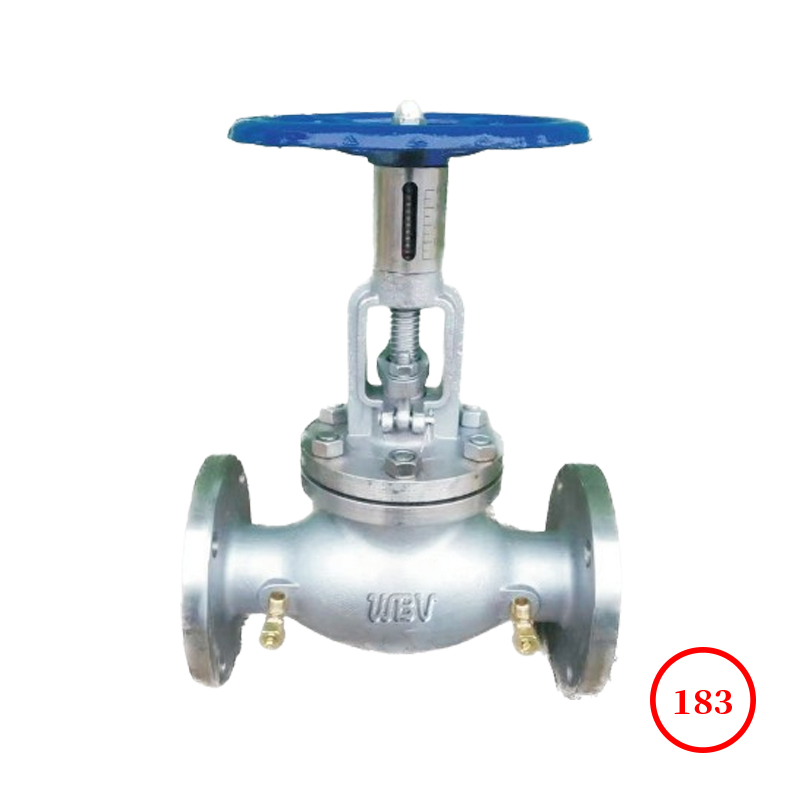
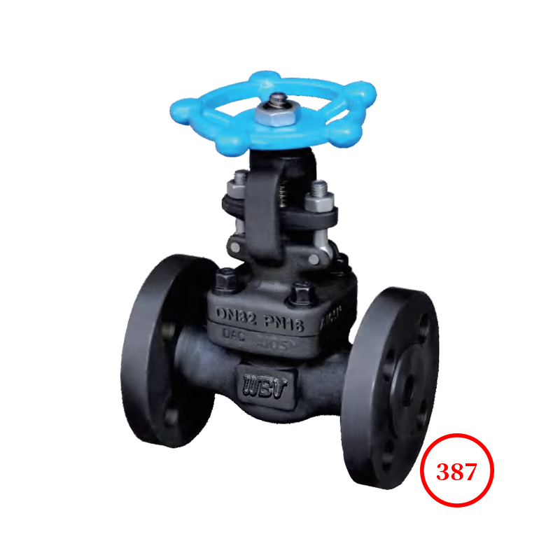
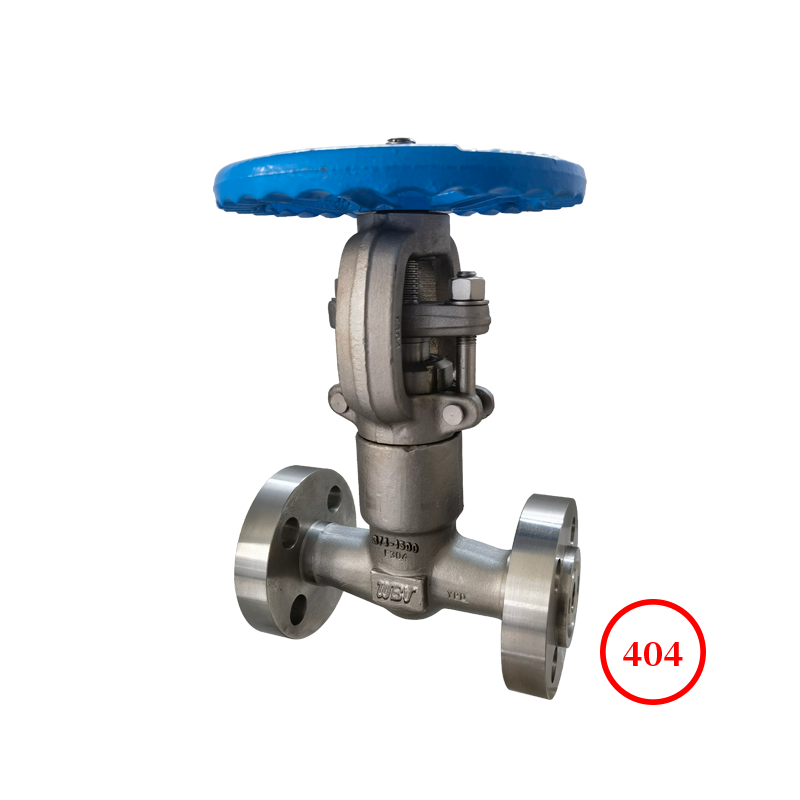
- Globe valve
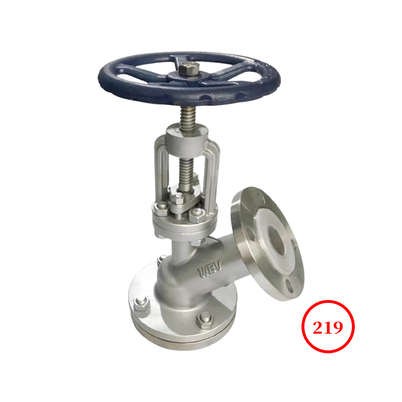
- Discharge valve
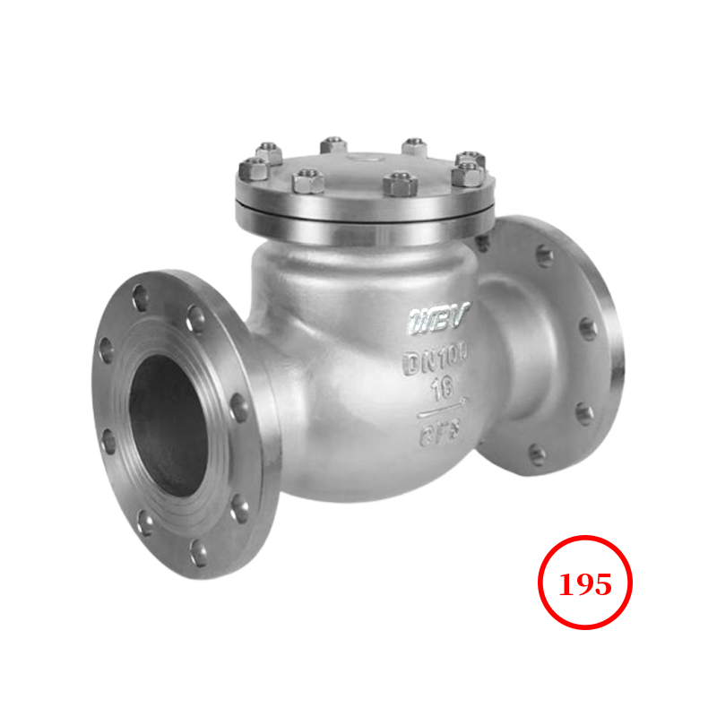
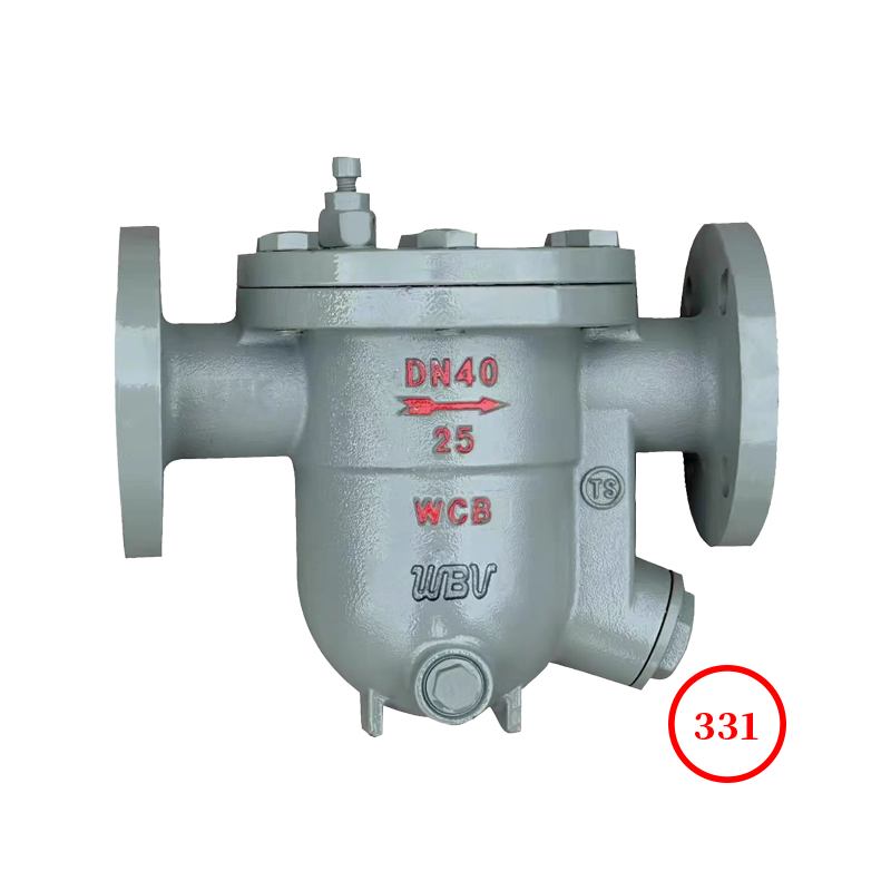
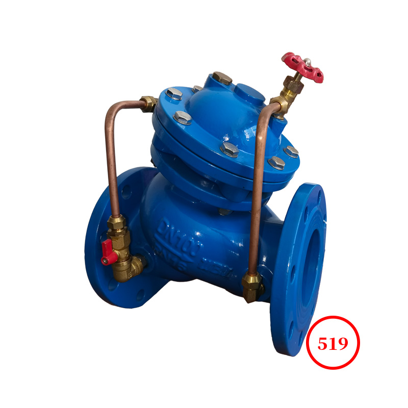
- Check valve
- Bottom valve
- Filter
- Butterfly valve
- Plunger valve
- Plug valve
- Insulated valve
- Low temperature valve
- Safety valve
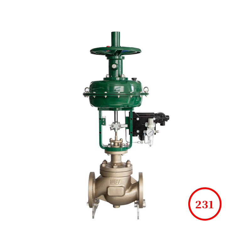
- Regulating valve
- Drain valve
- Pressure reducing valve
- Control valve
- Balance valve
- Copper valve
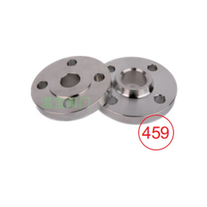
- Flange
- Slag discharge valve
- Sludge discharge valve
- News
- Equipment
- Honor
- Video
- Service
- Contact