Product Overview
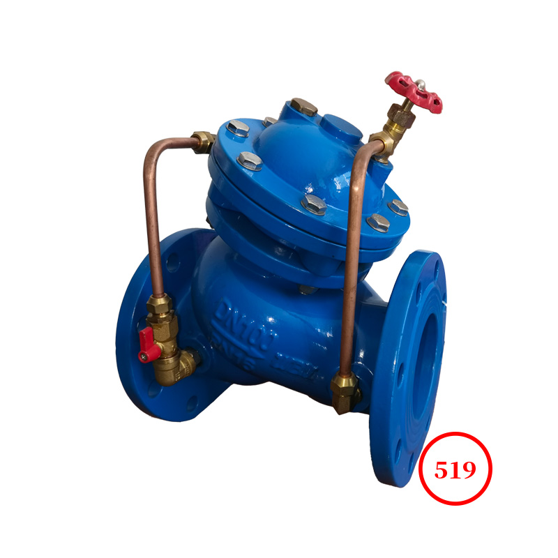
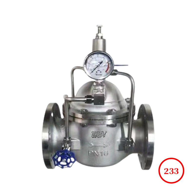
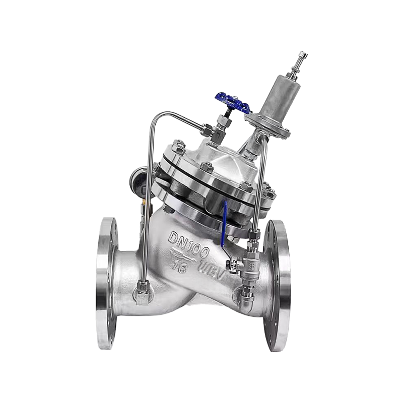
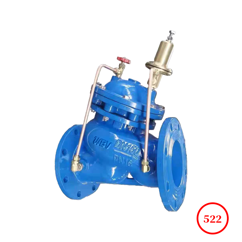
The 500 × pressure relief special pressure valve is mainly used in fire or other water supply systems to prevent system overpressure or maintain the pressure of the fire water supply system. After the fire pump is turned off, the impact of water hammer can be reduced. Also used for water hammer fire protection devices in large-scale water supply systems. And a self-cleaning filter screen is installed at the inlet of the valve control system, which utilizes fluid characteristics to prevent suspended particles with high density and diameter from entering the control system, ensuring smooth circulation and reliable operation of the cold door. The system operates smoothly, has high intensity, and has a long service life.
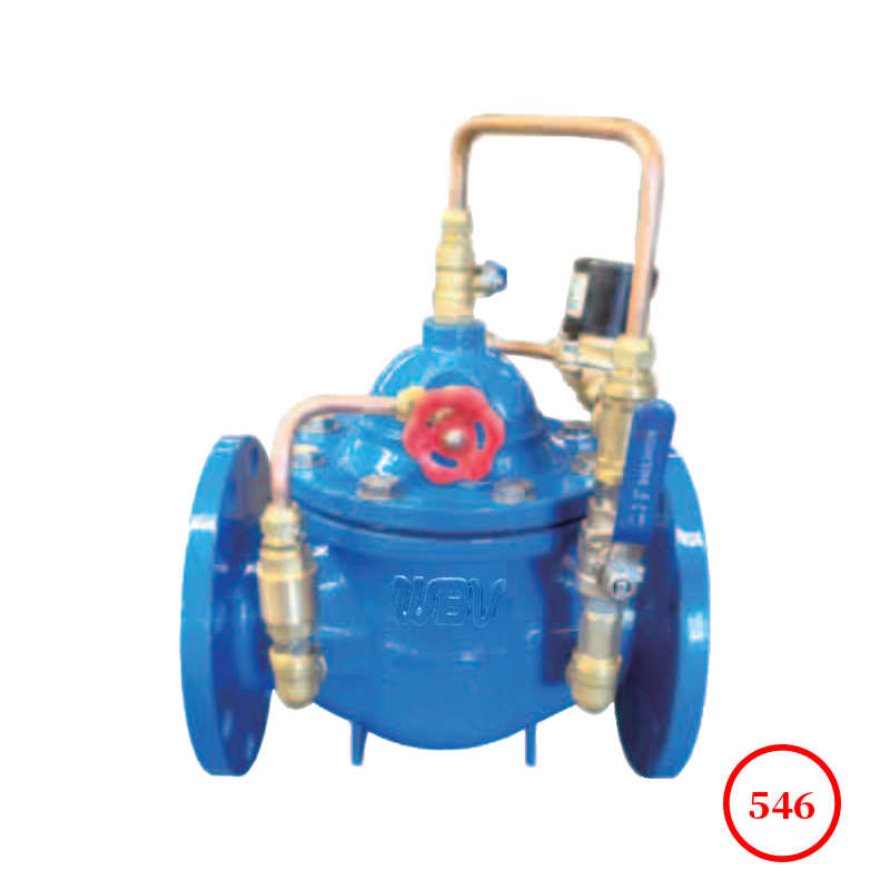
Structural characteristics and applications
The 500 × pressure relief valve consists of a main valve, a pressure relief/special pressure pilot valve needle valve, a ball valve, a micro filter, and a pressure gauge to form a hydraulic control connection system. By utilizing hydraulic automatic operation, it can be used as both a pressure relief valve and a pressure holding valve. When used as a pressure relief valve, it can maintain the water supply pressure below the set value; Used as a pressure holding valve, it can maintain the upstream water pressure of the main valve above the set value and maintain the upstream water supply pressure of the main valve. The 500 × pressure relief valve uses hydraulic self control, does not require other devices or energy, is easy to maintain, and can be used for multiple purposes with one valve. The 500X pool pressure valve product is widely used in water supply pipeline systems such as high-rise buildings and living areas, as well as urban water supply projects.
Product drawing

Product dimensions
| DN | L | PN10 | PN16 | PN25 |
| D | D1 | D2 | Z-Фd | D | D1 | D2 | Z-Фd | D | D1 | D2 | Z-Фd |
| 40 | 205 | 150 | 110 | 85 | 4-18 | 150 | 110 | 85 | 4-18 | 150 | 110 | 85 | 4-18 |
| 50 | 205 | 165 | 125 | 100 | 4-18 | 165 | 125 | 100 | 4-18 | 165 | 125 | 100 | 4-18 |
| 65 | 216 | 185 | 145 | 120 | 4-18 | 185 | 145 | 120 | 4-18 | 185 | 145 | 120 | 8-18 |
| 75 | 240 | 200 | 160 | 135 | 8-18 | 200 | 160 | 135 | 8-18 | 200 | 160 | 135 | 8-18 |
| 100 | 280 | 220 | 180 | 155 | 8-18 | 220 | 180 | 155 | 8-18 | 235 | 190 | 155 | 8-22 |
| 125 | 330 | 250 | 210 | 185 | 8-18 | 250 | 210 | 185 | 8-18 | 270 | 220 | 188 | 8-26 |
| 150 | 355 | 285 | 240 | 210 | 8-22 | 285 | 240 | 210 | 8-22 | 300 | 250 | 218 | 8-26 |
| 200 | 420 | 340 | 295 | 265 | 8-22 | 340 | 295 | 265 | 12-22 | 360 | 310 | 278 | 12-26 |
| 250 | 500 | 395 | 350 | 320 | 12-22 | 405 | 355 | 320 | 12-26 | 425 | 370 | 332 | 12-30 |
| 300 | 530 | 445 | 400 | 368 | 12-22 | 460 | 410 | 375 | 12-26 | 485 | 430 | 390 | 16-30 |
| 350 | 610 | 505 | 460 | 428 | 16-22 | 520 | 470 | 436 | 16-26 | 555 | 490 | 448 | 16-32 |
| 400 | 700 | 565 | 515 | 482 | 16-26 | 580 | 523 | 485 | 16-30 | 620 | 550 | 505 | 16-36 |
| 450 | 745 | 615 | 565 | 532 | 20-26 | 640 | 585 | 545 | 20-30 | 670 | 600 | 555 | 20-36 |
| 500 | 810 | 670 | 620 | 585 | 20-26 | 715 | 650 | 608 | 20-34 | 730 | 660 | 610 | 20-36 |
| 600 | 920 | 780 | 725 | 685 | 20-30 | 840 | 770 | 718 | 20-36 | 845 | 770 | 718 | 20-41 |
| 700 | 1195 | 895 | 840 | 800 | 24-30 | 910 | 840 | 788 | 24-36 | 960 | 875 | 815 | 24-42 |
Technical Documentation
1. Product design standard: CJ/T219-2005
2. Structural length standard: GB/T12221-2005
3. Flange standard: GB/T9113.1-2000
4. Test standard: GB/T13927-2022
Product Parts List
| serial number | name | material | serial number | name | material |
| 1 | Valve stem blockage | QT400 | 11 | rings | QT400 |
| 2 | valve body | QT400 | 12 | spring | 50CrVA |
| 3 | valve stem | 2Cr13 | 13 | ball valve | H59-1 |
| 4 | nut | 304 | 14 | Pressure relief valve | H59-1 |
| 5 | sealing element | NBR | 15 | needle valve | H59-1 |
| 6 | Valve disc | QT400+NR | 16 | pressure gauge | WCB+CP |
| 7 | Diaphragm pressure plate | QT400 | 17 | ball valve | H59-1 |
| 8 | diaphragm | NR+PA | 18 | bolt and nut | 304 |
| 9 | ball valve | H59-1 | 19 | filter | H59-1 |
| 10 | valve cover | QT400 | - | - | - |
Installation and adjustment (note during compression: 1. Needle valve open, 2. Three ball valves closed)
The best installation method for the main valve is horizontal installation, with the valve cover facing upwards. Other installation methods can also achieve the desired function. Before installation, the debris in the pipeline should be thoroughly removed. Pay attention to the installation direction of the flow direction indicator arrow outside the main valve body. After installation, it should be ensured that there is no pipeline stress acting on the valve body and internal components.
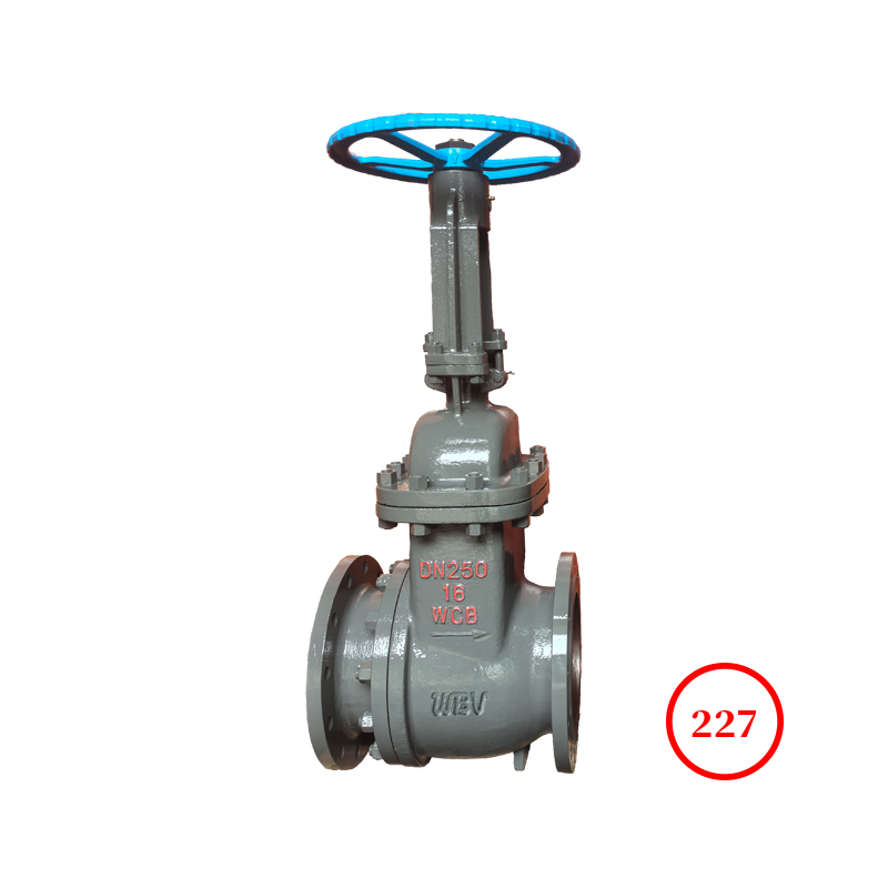
2. A gate valve and a filter should be installed in front of the main valve, and a gate valve should also be installed behind the main valve for easy maintenance.
Before adjusting the pressure, first open needle valve 15. When adjusting the pressure, loosen the locking nut under the pilot valve handwheel, then turn the pilot valve handwheel clockwise to increase the pressure, and vice versa to decrease the pressure. After adjusting, tighten the nut.
4. The pipeline must be thoroughly flushed before water supply.
5. The micro filter 18 should be cleaned regularly.