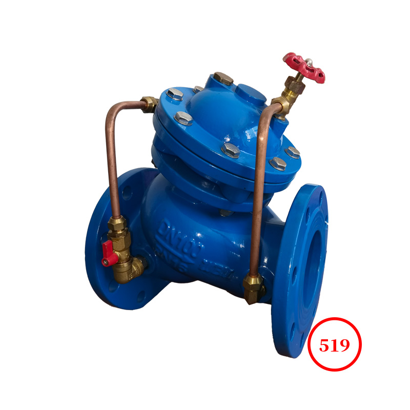
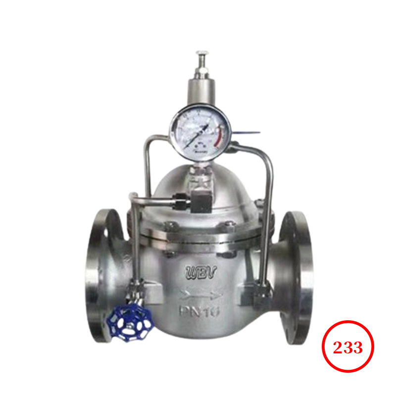
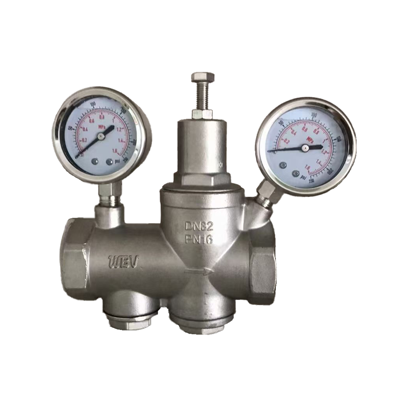
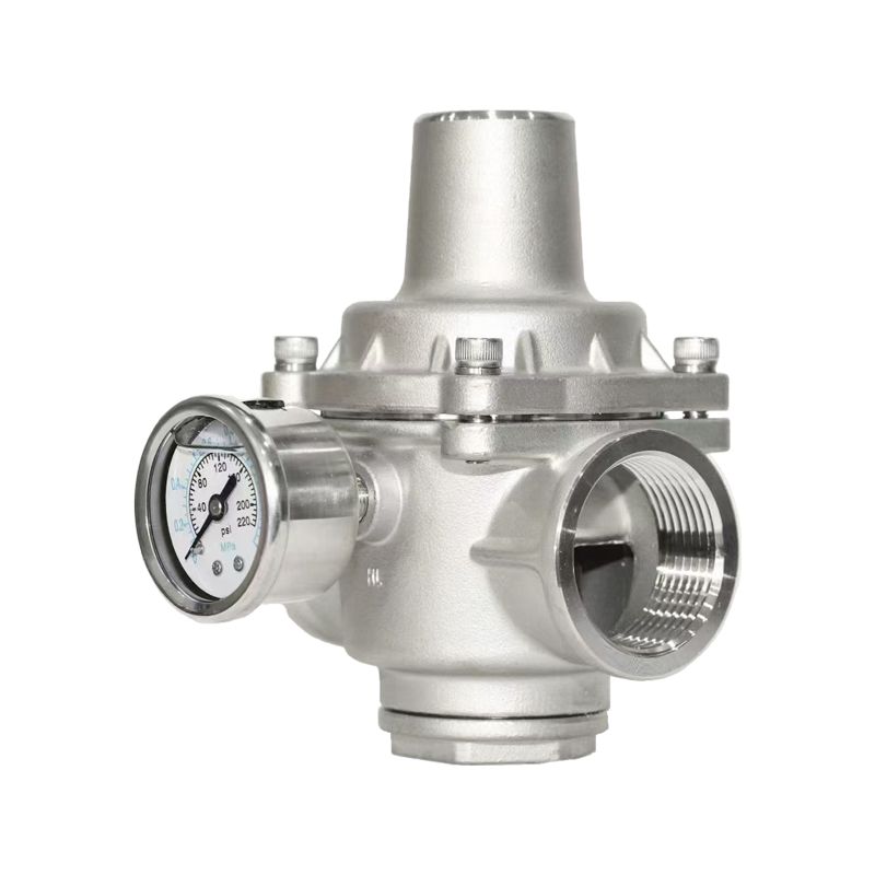
The 200X pressure reducing and stabilizing valve consists of a main valve, a pilot valve, a needle valve, a ball valve, a micro filter, and a pressure gauge to form a hydraulic control connection system. When in use, it can automatically maintain a stable outlet pressure after setting the outlet pressure. This product uses a pilot valve for self control, without the need for other devices or energy sources. It is easy to maintain, has high pressure control accuracy, is less affected by inlet pressure and flow rate, and has reliable pressure reduction and stabilization. Widely used in water supply network systems such as high-rise buildings, living areas, and urban water supply projects.
When the valve supplies water from the inlet end, water flows through the needle valve into the main valve control room, and the outlet pressure acts on the pilot valve through the conduit. When the outlet pressure is higher than the set value of the pilot valve spring, the pilot valve closes. The control room stops draining, and at this time, the pressure inside the main valve control room increases and the main valve is closed, and the outlet pressure no longer increases. When the outlet pressure of the valve drops to the set pressure of the pilot valve spring, the pilot valve opens and the control room drains downstream. Due to the drainage volume of the pilot valve system being greater than the inlet volume of the needle valve, the pressure in the main valve control room decreases. The import pressure causes the main valve to open. In a stable state, the control room has the same inlet and outlet water, the main valve opening remains unchanged, and the outlet pressure is stable.
Adjust the guide valve spring to set the outlet pressure.
Product drawing

Product dimensions
| DN | L | A | A1 | H | H1 | F | D | D1 | D2 | n-Φd |
| PN1.0 | PN1.6 | PN2.5 | PN1.0 | PN1.6 | PN2.5 | PN1.0 | PN1.6 | PN2.5 | PN1.0 | PN1.6 | PN2.5 |
| 20 | 180 | 292 | 136 | 342 | 247 | 116 | 105 | 105 | 105 | 75 | 75 | 75 | 58 | 58 | 56 | 4-13.5 | 4-13.5 | 4-14 |
| 25 | 180 | 292 | 136 | 342 | 247 | 116 | 115 | 115 | 115 | 85 | 85 | 85 | 68 | 68 | 65 | 4-13.5 | 4-13.5 | 4-14 |
| 32 | 180 | 292 | 136 | 342 | 247 | 116 | 140 | 140 | 140 | 100 | 100 | 100 | 78 | 78 | 76 | 4-17.5 | 4-17.5 | 4-18 |
| 40 | 240 | 330 | 155 | 395 | 278 | 170 | 150 | 150 | 150 | 110 | 110 | 110 | 88 | 88 | 84 | 4-17.5 | 4-17.5 | 4-18 |
| 50 | 240 | 330 | 155 | 395 | 278 | 170 | 165 | 165 | 165 | 125 | 125 | 125 | 102 | 102 | 99 | 4-17.5 | 4-17.5 | 4-18 |
| 65 | 250 | 350 | 165 | 405 | 298 | 180 | 185 | 185 | 185 | 145 | 145 | 145 | 122 | 122 | 118 | 4-17.5 | 4-17.5 | 8-18 |
| 80 | 285 | 365 | 175 | 430 | 313 | 210 | 200 | 200 | 200 | 160 | 160 | 160 | 133 | 133 | 132 | 8-17.5 | 8-17.5 | 8-18 |
| 100 | 360 | 410 | 195 | 510 | 350 | 275 | 220 | 220 | 235 | 180 | 180 | 190 | 158 | 158 | 156 | 8-17.5 | 8-17.5 | 8-22 |
| 125 | 400 | 455 | 220 | 560 | 365 | 310 | 250 | 250 | 270 | 210 | 210 | 220 | 184 | 184 | 184 | 8-17.5 | 8-17.5 | 8-26 |
| 150 | 455 | 475 | 230 | 585 | 420 | 355 | 285 | 285 | 300 | 240 | 240 | 250 | 212 | 212 | 211 | 8-22 | 8-22 | 8-26 |
| 200 | 585 | 530 | 255 | 675 | 450 | 460 | 340 | 340 | 360 | 295 | 295 | 310 | 268 | 268 | 274 | 8-22 | 12-22 | 12-26 |
| 250 | 650 | 623 | 300 | 730 | 470 | 500 | 395 | 405 | 425 | 350 | 355 | 370 | 320 | 320 | 330 | 12-22 | 12-26 | 12-30 |
| 300 | 800 | 700 | 340 | 760 | 490 | 580 | 445 | 460 | 485 | 400 | 410 | 430 | 370 | 370 | 389 | 12-22 | 12-26 | 16-30 |
| 350 | 860 | 840 | 415 | 840 | 526 | 640 | 505 | 520 | 555 | 460 | 470 | 490 | 430 | 430 | 448 | 16-22 | 16-26 | 16-33 |
| 400 | 960 | 880 | 430 | 910 | 570 | 715 | 565 | 580 | 620 | 515 | 525 | 550 | 482 | 482 | 503 | 16-26 | 16-30 | 16-36 |
| 450 | 1075 | 930 | 460 | 1030 | 610 | 780 | 615 | 640 | 670 | 565 | 585 | 600 | 532 | 550 | 548 | 20-26 | 20-30 | 20-36 |
| 500 | 1075 | 980 | 490 | 1135 | 665 | 830 | 670 | 715 | 760 | 620 | 650 | 660 | 585 | 585 | 609 | 20-26 | 20-33 | 20-36 |
| 600 | 1230 | 1060 | 530 | 1270 | 725 | 920 | 780 | 840 | 845 | 725 | 770 | 770 | 685 | 685 | 720 | 20-30 | 20-36 | 20-39 |
| 700 | 1650 | 1130 | 560 | 1460 | 865 | 980 | 895 | 910 | 960 | 840 | 840 | 875 | 800 | 800 | 820 | 24-30 | 24-36 | 24-42 |
| 800 | 1750 | 1230 | 610 | 1640 | 975 | 1050 | 1015 | 1025 | 1085 | 950 | 950 | 990 | 905 | 905 | 928 | 24-33 | 24-39 | 24-48 |
Technical Documentation
1. Product design standard: CJ/T219-2005
2. Structural length standard: GB/T12221-2005
3. Flange standard: GB/T9113.1-2000
4. Test standard: GB/T13927-2022
Product Parts List
| serial number | name | material | serial number | name | material |
| 1 | screw plug | CF8/WCB | 10 | Studs and nuts | CF8 |
| 2 | valve body | CF8/WCB | 11 | ball valve | CF8 |
| 3 | valve stem | CF8/2Cr13 | 12 | needle valve | CF8 |
| 4 | Micro filter | CF8 | 13 | spring | 50CrVA |
| 5 | sealing ring | NBR | 14 | rings | CF8/WCB |
| 6 | Valve disc | CF8/WCB | 15 | pilot valve | CF8 |
| 7 | pressure plate | CF8/WCB | 16 | Sensor pressure gauge | CF8 |
| 8 | Rubber film | EPDM | 17 | ball valve | CF8 |
| 9 | valve cover | CF8/WCB | - | - | - |
working principle
The inlet pressure P1 enters the control chamber of the main valve through the conduit and needle valve 16 (see structural diagram), and establishes a downward pressure F3. The outlet pressure P2 also acts under the diaphragm of the pilot valve 15 through the conduit and opposes the regulating spring of the pilot valve. When the downstream pressure exceeds the set value of the pilot valve spring, the pilot valve closes. When the water discharge in the control room is 0 and the variable pressure F3 reaches its maximum value, the main valve disc tightly presses the valve seat and the pressure reducing valve closes. When the downstream pressure is lower than the set value of the pilot valve spring, the pilot valve opens, and the pressure water in the control room will be discharged downstream through pilot valve 15 and ball valve 17. Due to the small opening of the needle valve (1/4~1/2) and the smaller diameter of the inlet duct compared to the outlet duct, the discharge rate is greater than the inlet pressure replenishment rate. As a result, the pressure F3 in the control room decreases, and the inlet pressure P1, which has been acting under the main valve disc 6, lifts the main valve disc and opens the pressure reducing valve. In a stable regulation state, the discharge amount is equal to the replenishment flow rate, the opening of the main valve remains unchanged, and the downstream pressure is stable.
Installation and adjustment
1. The best installation method for the main valve is to install it horizontally on the pipeline, with the valve cover facing upwards. Other installation methods can also achieve the desired function. Before installation, it is necessary to thoroughly remove any debris from the pipeline. Pay attention to the arrow indicating the water flow outside the main valve body and install it in the direction. After installation, it should be ensured that there is no pipeline pressure acting on the valve body and internal components.
2. A gate valve and a filter should be installed in front of the main valve, and a gate valve should also be installed behind the valve. For ease of maintenance.
3. The filter 18 on the main valve should be cleaned regularly.
4. The pipeline system must be thoroughly flushed before water supply.
5. Bypass valves should be installed for important water supply pipelines.
6. Pressure regulation method:
(1) Close the upstream isolation valve, open the downstream isolation valve to release pressure, and after reducing the downstream pressure by 0.1Mpa, close the downstream isolation valve;
(2) Turn the adjusting screw of the pilot valve to the topmost position;
(3) Slowly open the upstream isolation valve to full open;
(4) Slowly tighten the regulating valve downwards, and the outlet pressure will gradually increase until the set value is reached, then lock the regulating valve screw;
(5) If the pressure is adjusted too much, it must be readjusted from the first step, that is, it can only be adjusted from low pressure to high pressure.