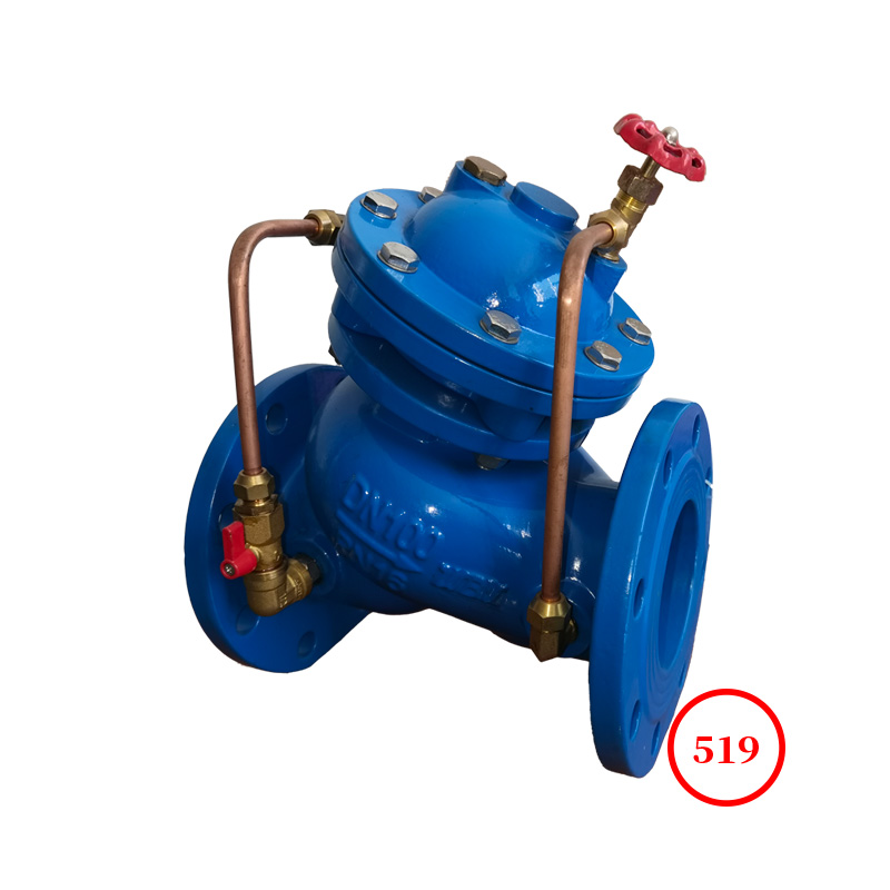
Yk43X/F series piston pressure reducing valve is suitable for pipelines with working temperature ≤ 80/150 ℃ for air, coal gas, liquefied gas, ammonia, oxygen, etc. This valve reduces the inlet pressure to a certain required outlet pressure through throttling of the opening and closing components, and uses the energy of the medium itself to automatically meet the predetermined requirements and adapt to the working conditions. The difference between the inlet pressure and outlet pressure of this valve must be ≥ 0.15MPa.
1. This valve consists of two main parts: a main valve and a pilot valve. The lower part of the main valve body has a lower cover, a main valve spring, and a main valve disc. The main valve disc is supported by the main valve spring to keep the main valve in a sealed state. The upper part of the main valve body has pistons, cylinder liners, etc. When the piston is subjected to medium pressure, it is guided by the cylinder liner to push the main valve disc, causing the valve to open; The valve body contains a valve spring, valve disc, diaphragm, etc. The valve spring supports the valve disc, keeping the valve in a sealed state; There are adjusting springs and bolts inside the cover of the pilot valve, which facilitate the adjustment of the required working pressure.
2. When this valve leaves the factory, the main valve and pilot valve are closed. When in use, rotate the adjusting bolt clockwise to open the pilot valve disc. The medium enters the pilot valve chamber through channel "a" and then enters channel "S". The piston is pushed by the medium pressure to open the main valve disc. The medium flows behind the valve and enters the diaphragm lower chamber through channel "B". When the pressure behind the valve exceeds the set pressure, the diaphragm is pushed to compress the regulating spring, and the pilot valve gradually closes. The medium flowing into the upper part of the piston decreases, and the piston rises, causing the main valve disc to gradually close under the action of the main valve spring. There is less medium flowing from chamber A to chamber B, and the pressure behind the valve decreases. The small change in pressure behind the valve affects the balance between the diaphragm and the regulating spring, causing the diaphragm to move up and down, pushing the pilot valve and piston to work, causing the main valve to move up and down to control the flow of medium. Therefore, the pressure behind the valve remains stable.
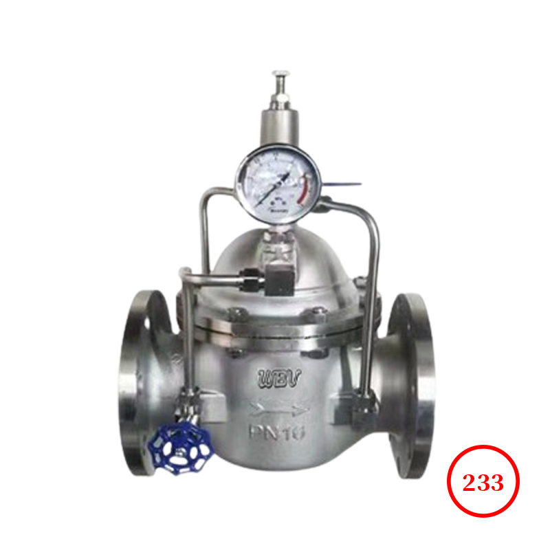
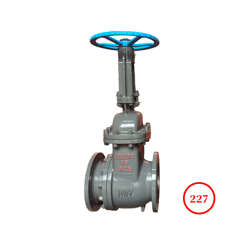
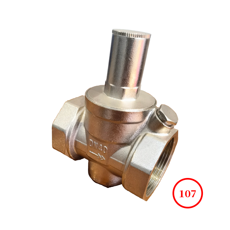
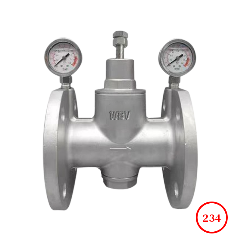
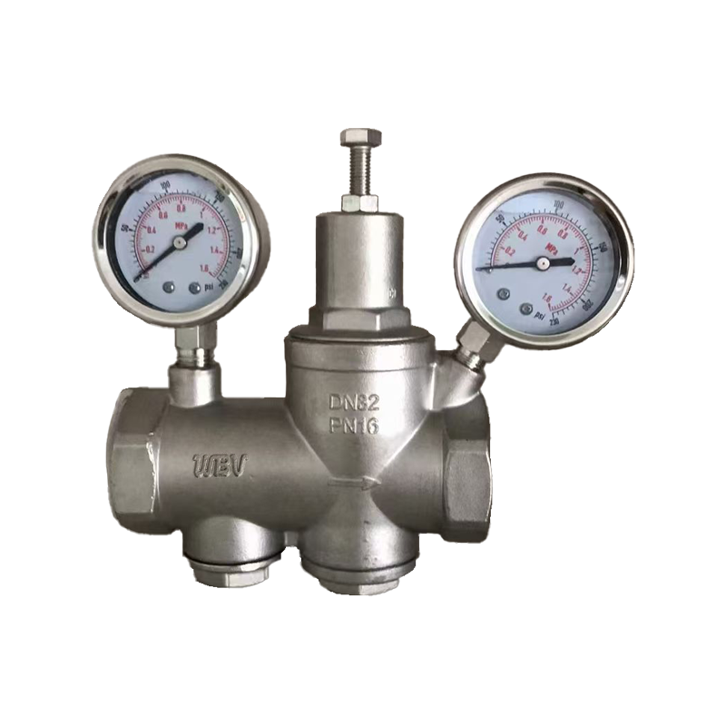
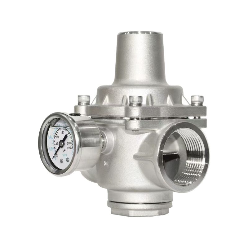
Product drawing

Product dimensions
| DN | PN16 | PN25 | PN40 | PN64 | PN16 | PN25 | PN40 | PN64 | PN16 | PN25 | PN40 | PN64 |
| L | H | h |
| 15 | 160 | 160 | 180 | 180 | 305 | 305 | 305 | 305 | 95 | 95 | 95 | 95 |
| 20 | 160 | 160 | 180 | 180 | 305 | 305 | 305 | 305 | 95 | 95 | 95 | 95 |
| 25 | 180 | 200 | 200 | 200 | 305 | 305 | 305 | 305 | 95 | 95 | 95 | 95 |
| 32 | 200 | 200 | 220 | 220 | 305 | 305 | 305 | 305 | 95 | 95 | 95 | 95 |
| 40 | 220 | 220 | 240 | 240 | 330 | 330 | 330 | 330 | 110 | 110 | 110 | 110 |
| 50 | 250 | 250 | 270 | 270 | 330 | 330 | 330 | 330 | 110 | 110 | 110 | 110 |
| 65 | 260 | 260 | 280 | 300 | 330 | 330 | 330 | 330 | 110 | 110 | 110 | 110 |
| 80 | 310 | 310 | 330 | 330 | 355 | 355 | 355 | 355 | 155 | 155 | 155 | 155 |
| 100 | 350 | 350 | 380 | 380 | 355 | 355 | 355 | 355 | 155 | 155 | 155 | 155 |
| 125 | 400 | 400 | 450 | 450 | 420 | 420 | 420 | 420 | 200 | 200 | 200 | 200 |
| 150 | 450 | 450 | 500 | 500 | 420 | 420 | 420 | 420 | 200 | 200 | 200 | 200 |
| 200 | 500 | 500 | 560 | 560 | 475 | 475 | 475 | 475 | 230 | 230 | 230 | 230 |
| 250 | 600 | 600 | - | - | 510 | 510 | 510 | 510 | 280 | 280 | 280 | 280 |
| 300 | 800 | 800 | - | - | 560 | 560 | 560 | 560 | 320 | 320 | 320 | 320 |
Technical Documentation
1. Implement the standard GB/T 12244-2006
2. Structural length standard: GB/T12221-2005
3. Flange standard: GB/T9113.1-2000
4. Test standard: GB/T13927-2022
Product Parts List
| serial number | name | material | serial number | name | material |
| 1 | Valve body, valve cover, bottom cover | WCB/CF8 | 6 | valve stem | 2Cr13 |
| 2 | valve seat | 2Cr13/304SS | 7 | diaphragm | 304SS |
| 3 | valve disc | 2Cr13/304SS | 8 | spring | 60Si2Mn |
| 4 | cylinder liner | 2Cr13/304SS | 9 | gasket | NBR/PTFE |
| 5 | piston | 2Cr13/304SS | 10 | Guide valve body, guide valve cover | 25#/304SS |
Installation and usage precautions
1. Before installing this valve, carefully check whether the usage is consistent with the label requirements;
2. This valve is installed on a horizontal pipeline, and the arrow on the valve body should be consistent with the flow direction of the medium;
3. There should be a straight pipe before and after the pressure reducing valve, with a diameter of 0.6 × DN or more in front of the valve and 10 × DN or more behind the valve. A typical installation is shown in the following figure:

4. The following tasks should be carried out during installation:
(1) Remove the covers at both ends of the valve;
(2) Check the connecting bolts for looseness;
(3) The pipeline in front of the valve must be flushed clean.
5. This valve is only used for pressure reduction on the pipeline, not for shut-off. The medium used must be filtered through a filter;
6. When in use, slowly rotate the adjusting screw clockwise to increase the outlet pressure to the desired level. After adjustment, tighten the screw.
Pressure regulation method
1. Close the gate valve before the pressure reducing valve and open the gate valve after the pressure reducing valve to create a downstream low-pressure environment;
2. Rotate the adjusting screw counterclockwise to the highest position (relative to the lowest outlet pressure), and then close the pressure reducing valve and gate valve;
3. Slowly open the gate valve in front of the pressure reducing valve until fully open;
4. Slowly rotate the adjusting screw clockwise to adjust the outlet pressure to the desired pressure (based on the gauge pressure behind the valve); After adjustment, tighten the locking nut and open the pressure reducing valve and gate valve;
5. If the outlet pressure is higher than the set pressure during adjustment, it must be readjusted from the first step, that is, it can only be adjusted from low pressure to high pressure.
Possible faults and their elimination methods
| fault content | Reason for malfunction | Elimination methods |
| unventilated | a,B,S channels are blocked | Eliminate channel dirt |
| Direct gas flow | piston seizure | Eliminate dirt between cylinder liner and piston |
| The main and pilot valve stems are stuck in the pilot holes | Sand the main and pilot valve stems with fine sandpaper to reduce the outer diameter |
| There is dirt stuck on the sealing surface of the main and pilot valves | Eliminate dirt on the seals of the main and pilot valves |
| Damaged membrane | Replace the membrane |
| Is the bypass valve closed | Close the bypass valve |
| The pressure cannot be adjusted high | Excessive clearance between cylinder liner and piston | Replace cylinder liner or piston |
| Adjust spring fatigue or damage | replace the spring |
| Unstable pressure behind the valve | Excessive fluctuations in export flow | Flow rate after stabilizing valve |
| The difference between input and consumption is too large | Re select the valve diameter |