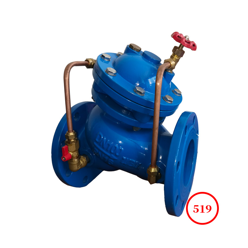
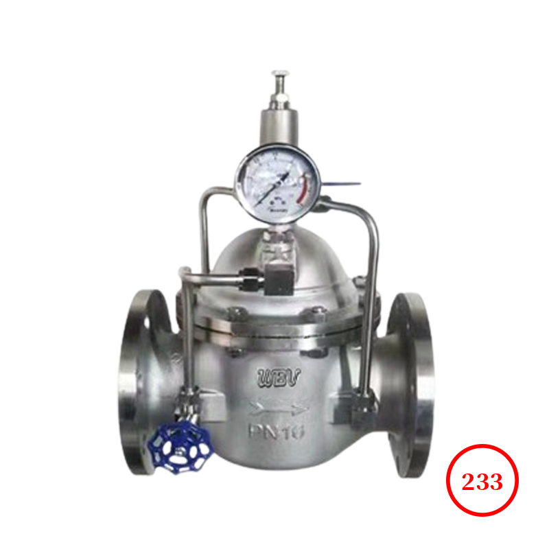
The flow control valve consists of a main valve, a flow regulating valve, a needle valve, a pilot valve, a ball valve, a micro filter, and a pressure gauge to form a hydraulic control connection system. Using hydraulic automatic operation to control and regulate the opening of the main valve, keeping the flow rate through the main valve constant.
This product utilizes hydraulic self control, does not require other devices or energy, is easy to maintain, and has stable flow control.
This series of valve products is widely used in water supply network systems such as high-rise buildings and living areas, as well as urban water supply projects.
The flow control valve is operated by the pressure of the pipeline itself. When the valve supplies water from the inlet end, the water flows through the needle valve into the main valve control chamber, and flows out of the main valve control chamber to the outlet through the pilot valve and ball valve. At this time, the main valve is in a fully open or floating state. The flow control valve on the upper part of the main valve can be set to a certain opening degree. By adjusting the needle valve opening and the pressure of the pilot valve spring, the main valve opening can be kept at the set opening, and the pilot valve will automatically adjust when the pressure changes to maintain the same flow rate.
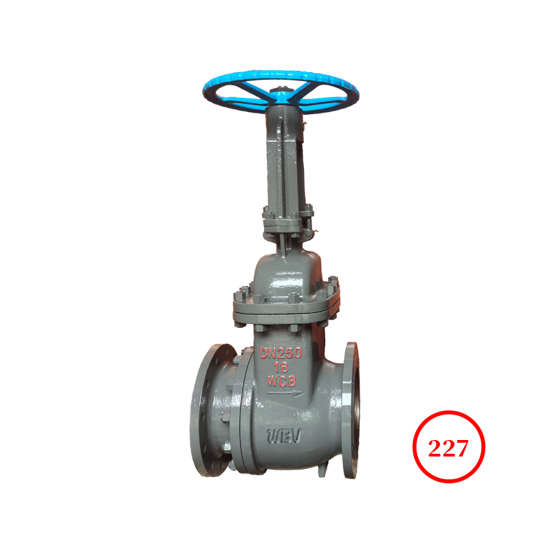
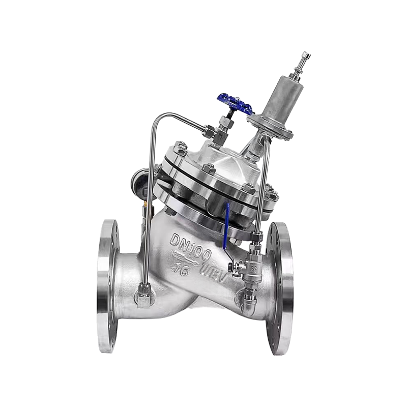
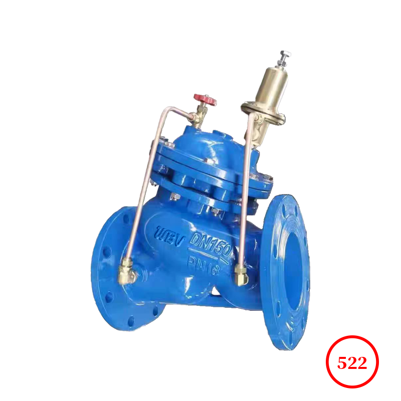
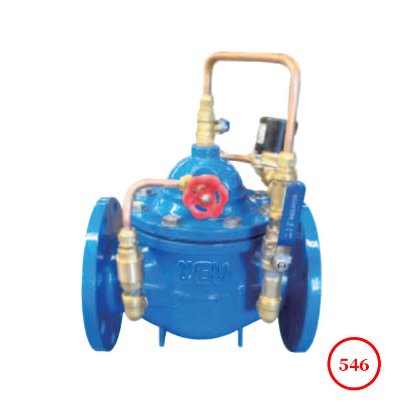
Product drawing

Product dimensions
| DN | L | A | A1 | H | H1 | F | D | D1 | D2 | n-Фd |
| PN1.0 | PN1.6 | PN2.5 | PN1.0 | PN1.6 | PN2.5 | PN1.0 | PN1.6 | PN2.5 | PN1.0 | PN1.6 | PN2.5 |
| 20 | 180 | 292 | 136 | 342 | 247 | 116 | 105 | 105 | 105 | 75 | 75 | 75 | 58 | 58 | 56 | 4-13.5 | 4-13.5 | 4-14 |
| 25 | 180 | 292 | 136 | 342 | 247 | 116 | 115 | 115 | 115 | 85 | 85 | 85 | 68 | 68 | 65 | 4-13.5 | 4-13.5 | 4-14 |
| 32 | 180 | 292 | 136 | 342 | 247 | 116 | 140 | 140 | 140 | 100 | 100 | 100 | 78 | 78 | 76 | 4-17.5 | 4-17.5 | 4-18 |
| 40 | 240 | 330 | 155 | 395 | 278 | 170 | 150 | 150 | 150 | 110 | 110 | 110 | 88 | 88 | 84 | 4-17.5 | 4-17.5 | 4-18 |
| 50 | 240 | 330 | 155 | 395 | 278 | 170 | 165 | 165 | 165 | 125 | 125 | 125 | 102 | 102 | 99 | 4-17.5 | 4-17.5 | 4-18 |
| 65 | 250 | 350 | 165 | 405 | 298 | 180 | 185 | 185 | 185 | 145 | 145 | 145 | 122 | 122 | 118 | 4-17.5 | 4-17.5 | 8-18 |
| 80 | 285 | 365 | 175 | 430 | 313 | 210 | 200 | 200 | 200 | 160 | 160 | 160 | 133 | 133 | 132 | 8-17.5 | 8-17.5 | 8-18 |
| 100 | 360 | 410 | 195 | 510 | 350 | 275 | 220 | 220 | 235 | 180 | 180 | 190 | 158 | 158 | 156 | 8-17.5 | 8-17.5 | 8-22 |
| 125 | 400 | 455 | 220 | 560 | 365 | 310 | 250 | 250 | 270 | 210 | 210 | 220 | 184 | 184 | 184 | 8-17.5 | 8-17.5 | 8-26 |
| 150 | 455 | 475 | 230 | 585 | 420 | 355 | 285 | 285 | 300 | 240 | 240 | 250 | 212 | 212 | 211 | 8-22 | 8-22 | 8-26 |
| 200 | 585 | 530 | 255 | 675 | 450 | 460 | 340 | 340 | 360 | 295 | 295 | 310 | 268 | 268 | 274 | 8-22 | 12-22 | 12-26 |
| 250 | 650 | 623 | 300 | 730 | 470 | 500 | 395 | 405 | 425 | 350 | 355 | 370 | 320 | 320 | 330 | 12-22 | 12-26 | 12-30 |
| 300 | 800 | 700 | 340 | 760 | 490 | 580 | 445 | 460 | 485 | 400 | 410 | 430 | 370 | 370 | 389 | 12-22 | 12-26 | 16-30 |
| 350 | 860 | 840 | 415 | 840 | 526 | 640 | 505 | 520 | 555 | 460 | 470 | 490 | 430 | 430 | 448 | 16-22 | 16-26 | 16-33 |
| 400 | 960 | 880 | 430 | 910 | 570 | 715 | 565 | 580 | 620 | 515 | 525 | 550 | 482 | 482 | 503 | 16-26 | 16-30 | 16-36 |
| 450 | 1075 | 930 | 460 | 1030 | 610 | 780 | 615 | 640 | 670 | 565 | 585 | 600 | 532 | 550 | 548 | 20-26 | 20-30 | 20-36 |
| 500 | 1075 | 980 | 490 | 1135 | 665 | 830 | 670 | 715 | 730 | 620 | 650 | 660 | 585 | 585 | 609 | 20-26 | 20-33 | 20-36 |
| 600 | 1230 | 1060 | 530 | 1270 | 725 | 920 | 780 | 840 | 845 | 725 | 770 | 770 | 685 | 685 | 720 | 20-30 | 20-36 | 20-39 |
| 700 | 1650 | 1130 | 560 | 1460 | 865 | 980 | 895 | 910 | 960 | 840 | 840 | 875 | 800 | 800 | 820 | 24-30 | 24-36 | 24-42 |
| 800 | 1750 | 1250 | 610 | 1640 | 975 | 1050 | 1015 | 1025 | 1085 | 950 | 950 | 990 | 905 | 905 | 928 | 24-33 | 24-39 | 24-48 |
Technical Documentation
1. Product design standard: CJ/T219-2005
2. Structural length standard: GB/T12221-2005
3. Flange standard: GB/T9113.1-2000
4. Test standard: GB/T13927-2022
Product Parts List
| Number | Name | Material | Number | Name | Material |
| 1 | valve body | CF8/WCB | 9 | spring | CF8 |
| 2 | valve stem | CF8/2Cr13 | 10 | diaphragm | EPDM |
| 3 | hex nut | CF8/A105 | 11 | valve cover | CF8/WCB |
| 4 | valve seat | CF8/1Cr13 | 12 | needle valve | CF8 |
| 5 | O-ring | NBR | 13 | ball valve | CF8 |
| 6 | sealing ring | NBR | 14 | float valve | CF8 |
| 7 | valve disc | CF8/WCB | 15 | micro filter | CF8 |
| 8 | Diaphragm pressure sleeve | CF8/WCB | - | - | - |
Key points for selecting flow control valves
The hydraulic control valve used in engineering is a product that has been inspected and qualified by the manufacturer, has complete identification, and meets the technical requirements.
(2) Based on functional requirements, select the type of valve, and then determine the material of the valve body and sealing parts according to the pipeline conveying medium, temperature, building standards, and owner requirements. Common valve body materials include cast iron, copper iron, copper, plastic, etc. Common sealing surfaces and lining materials include copper alloy, plastic, steel, hard alloy, rubber, etc. The valve body material should match the pipeline material.
(3) The nominal pressure of valves varies in different levels such as 0.6, 1.0, 1.6, 2.5, and 4.0 MPa. The working pressure of the medium transported by pipelines should be lower than the nominal pressure value of the valve.
(4) The installation of hydraulic control valves in engineering should have sufficient space for management, operation, installation, and maintenance, and should comply with the requirements of pipelines for valves.
(5) When using flange connections for pipelines, hydraulic control valves with flange connections should be used; When using groove type connections for pipelines, hydraulic control valves with groove type connections should be used.
(6) Water control valves should be installed on pipelines with unidirectional flow of the medium.
(7) The direction of the arrow on the main valve body of the hydraulic control valve must be consistent with the flow direction of the pipeline system.
(8) There should be no air blockage or obstruction in the hydraulic control valve pipe section. Automatic exhaust valves should be installed in gas storage sections such as pipeline locations.
(9) When installing the valve horizontally, the valve cover and stem should face upwards. When installed vertically, the valve cover and stem should face outward.
(10) Strength and tightness tests should be conducted before valve installation.
(11) The strength and tightness tests of valves shall comply with the following regulations.
A、 The strength test pressure of the valve is 1.5 times the nominal pressure;
B、 The tightness test pressure of the valve is 1.5 times the nominal pressure;
C、 The test pressure should remain constant during the duration of the test, and there should be no leakage on the shell packing and valve disc sealing surface;
D、 The duration of valve testing shall be as shown in the table above.